Ques 51. Alternators are usually designed to generate which type of ac voltage?
With fixed frequency
With variable frequency
Fixed current
Fixed power factor
Answer.1.With fixed frequency
Explanation:
In an alternating current electric power system, synchronization is the process of matching the speed and frequency of a generator or other source to a running network. An AC generator cannot deliver power to an electrical grid unless it is running at the same frequency as the network. If two segments of a grid are disconnected, they cannot exchange AC power again until they are brought back into exact synchronization.
Hence alternators are usually designed with the fixed frequency of AC voltage.
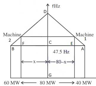
Ques 52. Two alternators rated 40 MVA and 60 MVA respectively are working in parallel and supplying a total load of 80 MW. Speed regulation of both the alternator is 5%. The load sharing between them will be
30 MW, 50 MW
32 MW, 48 MW
36 MW, 44 MW
40 MW each
Answer. 2.32 MW, 48 MW
Explanation:-
Change in frequency from No load to full load
f = 50 x 0.05 = 2.5Hz
Full load frequency
ffl1 = 50 – 2.5 = 47.5Hz
Since both alternators have same speed regulation then
ffl1 = ffl2
From the above diagram
For machine 1
(50 – f)/(80 – x) = (50 – 47.5)/40
x – 16f = 80 – 16 x 50
x- 16f = -720—–1
For machine 2
(50 – f)/(80 – x) = (50 – 47.5)/60
x – 24f = -1200 ——-2
From equation (1) and (2)
x= 48 MW
f = 60 Hz
So, machine A operates at a load of 48 MW While machine B will operate at a load of
80 – 48 = 32 MW
Ques 53. An alternator has a per unit impedance of 0.9 p.u. to a base of 20 MVA, 33 kV, Then the p.u. impedance to the base of 50 MVA and 11 kV.
Ques 54. In an alternator, the effect of armature reaction is minimum at the power factor of
0.5 Lagging
0.866 Lagging
0.866 Leading
Unity
Answer.4.Unity
Explanation:-
At unity p.f., the effect of armature reaction is merely to distort the main field; there is no weakening of the main field and the average flux practically remains the same.
At zero p.f. lagging, armature reaction is directly demagnetizing and the armature reaction weakens the main flux. This causes a reduction in the generated e.m.f.
At zero p.f. leading, armature flux is now in the same direction as the field flux and, therefore the armature reaction strengthens the main flux. This causes an increase in the generated voltage.
Ques 55. The armature leakage reactance is a parameter that accounts for that part of the ______ produced by the armature
Magnetic flux
Armature Flux
Magnetic and Armature flux
None of the above
Answer.1.Magnetic Flux
Explanation:-
The armature leakage reactance is a parameter that accounts for that part of the magnetic flux produced by the armature that does not cross the air gap to link with the rotor winding. The flux leakage is formed by end-winding leakage, slot leakage, and tooth tip leakage fluxes.
Ques 56. Turbo alternators have rotors of
Small diameter and long axial length
Large diameter and long axial length
Large diameter and small axial length
Small diameter and axial length
Answer. 1.Small diameter and long axial length
Explanation:-
Smooth Cylindrical Type or Non-Salient Pole alternator rotor is used for steam-driven alternator i.e turbo alternator which runs at very high speed.
This type of Rotor is used for steam-driven alternator i.e turbo alternator which runs at very high speed.
The Rotor is made up of smooth solid forgings of alloy steel cylinder having a number of slots along the outer periphery.
The field windings of the cylindrical type rotor are connected in series to the slip rings through which they are excited by the DC exciter.
The top portion of the slot is covered with the help of steel or manganese wedges and the unslotted portion of the cylinder acts as the poles of an alternator.
The field windings are arranged in such a way that their flux density is maximum on the polar central line.
In the cylindrical rotor, the pole doesn’t project out from the smooth surface of the rotor hence they maintain the uniform air gap between the stator and rotor.
Since the steam turbine runs at a very high speed, therefore, they required less number of poles hence the diameter of the rotor is small, and the axial or rotor length is large.
Ques 57. The steady-state fault current during a 3 phase terminal fault on a generator is determined by:
The transient reactance of the generator
The Sub-transient reactance of the generator
The synchronous reactance of the generator
DC offset during the instant of the fault
Answer.3.The synchronous reactance of the generator
Explanation:-
Sub-transient (xd”). Subtransient reactance is a value used to determine the short circuit current during the first few cycles after a short-circuit occurs. This is the short-circuit current value to be used in all short-circuit studies.
Transient reactance (Xd’). Transient reactance is a value used to determine the short-circuit current from the first few cycles up to about 30 cycles after the short-circuit occurs (depending upon the design of the machine). This value is often used in voltage regulation studies.
Synchronous reactance (Xd). Synchronous reactance is a value used to determine the short-circuit current when the steady-state condition has been reached. Steady-state is reached several seconds afier the shortcircuit occurs. This value is often used to determine the setting of the generator backup overcurrent relays.
Ques 58. To reduce the peripheral speed of an alternator, the diameter of the rotor is
Increased
Decreased
Increased or decreased
Kept the same
Answer 2.Decreased
Explanation:-
Peripheral speed refers to the actual linear speed of a tooth or point of the circumference of an alternator when it is revolving under power. Peripheral speed is thus the product of the circumference of the alternator and the number of revolutions per minute.
The peripheral speed of the alternator
Ps = π × D × RPM
The peripheral speed depends on the speed as well as the diameter of the rotor. So to reduce the peripheral speed of the alternator the diameter of the rotor should be decreased.
Ques 59. The positive, negative, and zero sequence impedances of the 3-phase synchronous generator are j 0.5 pu, j 0.3 pu, and j 0.2 pu respectively. When the symmetrical fault occurs on the machine terminals. Find the fault current. The generator neutral is grounded through reactance of j0.1 pu
-j 3.33 pu
-j 1.67 pu
-j2.0 pu
-j 2.5 pu
Answer. 2. -j 1.67 pu
For symmetrical fault, the fault current is given as
If = E/(Zi +Zn)
Where E = Pre fault voltage Which is equal to 1
Zi = poisitive impedance Zn = Neutral Impedance
Zi = 0.5j & Zn = 0.1 j
If = 1/(0.5j + 0.1j)
If = -j 1.67
Ques 60. The emf induced per phase in a three-phase star-connected synchronous generator having the following data
Distribution factor = 0.955
Coil-span factor = 0.966
Frequency = 50 Hz
Flux per pole = 25 mwb
Turns per phase = 240, then emf per phase is
2128.36 Volts
1228.81 Volt
869.46 Volts
1737.80 Volts
Answer. 2.1228.81 volt
Explanation:-
E.M.F Equation of an alternator is given as
E = Kc Kd √2π f Φ Np
Or E = 4.44 Kc Kd f Φ Np ………….. (since √2π = 4.44)