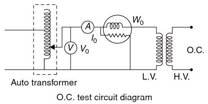
The current drawn by shunt parameters in a transformer is no-load current. Therefore the current that will flow in the circuit in the open circuit test is very low so the measurement of the quantities voltage, current, and power must be in the low voltage side so that the corresponding value will be readable in the instruments. And therefore, the open circuit test must be performed on the low voltage side. This means the high voltage side must be kept open.
As the normal rated voltage is applied to the primary, therefore, normal iron losses will occur in the transformer core. Hence wattmeter will record the iron losses and small copper loss in the primary. Since the no-load current is very small (usually 2 — 10% of rated current), Cu losses in the primary under no-load condition are negligible as compared with iron losses. Hence, wattmeter reading practically gives the iron losses in the transformer It is reminded that iron losses are the same at all loads.
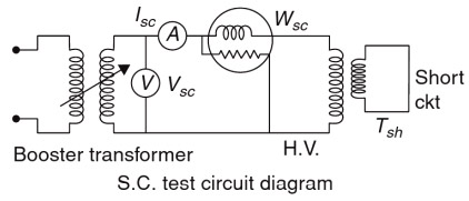
Short-Circuit Test
The short-circuit test on the transformer is performed to determine the equivalent resistance and leakage reactance either referred to the primary side or referred to the secondary side.
Since the H.V. rated current is less, a short-circuit test is conducted preferably on H.V. side keeping L.V short-circuited. For conducting a short-circuit test only a small percentage (of the order 5% to 10%) of the rated voltage is sufficient to cause the rated current to flow through the windings. As the voltage is less, the core flux density is very much less compared to the normal value, so the iron loss which depends on flux density (voltage) can be neglected. The input is therefore equal to the total copper loss.
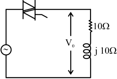
Ques.2. A triac based single-phase voltage regulator feeds an R-L load as shown in the figure. What is the range of triggering angle for which the output voltage Vo is not controllable?
45° ≤ α ≤ 180°
45° ≤ α ≤ 90°
0° ≤ α ≤ 45°
90° ≤ α ≤ 180°
Answer.3. 0° ≤ α ≤ 45°
Explanation:-
For controlling the load, the minimum value of firing angle α = load phase angle.
Phase angle φ = tan−1(ωL/R)
φ = tan−1(10/10) = 45°
The firing angle for which the output voltage is uncontrollable is
0 ≤ αmin ≤ φ
0° ≤ α ≤ 45°
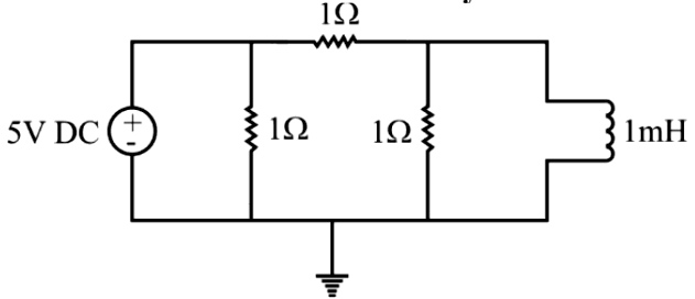
Ques.3. In the given circuit with the shown ideal 5V DC source, the magnitude of the total current drawn from the source at a steady-state is
2.5 A
5 A
10 A
7.5 A
Answer.3. 10 A
Explanation:-
Under steady-state conditions, the inductor is replaced by short-circuited. Therefore, a 1 Ω resistor that is connected parallel to the nductor is neglected.
Hence total resistance of the circuit will be
Rtotal = 1Ω || 1Ω = (1 × 1)/(1 + 1)
Rtotal = 0.5
Therefore current drawn by the 5 V source is
I = V/R = 5/0.5
I = 10 A
Ques.4. The impulse response of a causal linear time-invariant system is given as h(t). Now consider the following two statements and answer which of the following is true?
P: The system satisfies the superposition principle
Q: h(t) = 0 for t < 0
P is false and Q is true
P is false and Q is false
Pis true and Q is false
P is true and Q is true
Answer.4. P is true and Q is true
Explanation:-
A system is said to be a linear time-invariant (LTI) system if it follows the superposition principle.
Superposition Principle: If y1 and y2 are the responses to the input sequences x1 and x2, respectively, then the input ax1 + bx2 produces the response ay1 + by2.
The superposition principle allows us to study the behavior of a linear system starting from test signals such as impulses or sinusoids and obtaining the responses to complicated signals by weighted sums of the basic responses. A linear system is said to be linear time-invariant (LTI), if a time shift in the input results in the same time shift in the output or, in other words if it does not change its behavior in time.
Casual System
A system is said to be causal if the output of the system depends only on the input at the present time and/or in the past, but not the future value of the input. Thus, a causal system is non-anticipative, i.e. output cannot come before the input.
To have the given system to be causal, its impulse response must be zero for t < 0. The impulse occurs at t = 0 and there should not be output without input. Thus if h(t) is the system response to an impulse input then for causal system h(t) = 0 for t < 0. This is the required condition for the causal system.
h(t) = 0 for t < 0
Thus both the above condition is satisfied i.e
P: The system satisfies the superposition principle
Q: h(t) = 0 for t < 0
Ques.5. What is the total electric flux through the surface of a sphere that has a radius of 1 m and carries a charge of 1µC at its center? coulomb constant is given by Ke = 1/4πεο = 8.99 × 10⁹ where εο is the permittivity of free space.
1.13 × 10⁵ Nm2/C
8.99 × 10³ Nm2/C
3.98 × 10³ N/C
0.28 × 10⁵ Nm2
Answer.1. 1.13 × 10⁵ N.m2/C
Explanation:-
Charge (q) = 1 × 10⁻⁶ C
εο = 8.854 × 10⁻¹²
The electric flux through the surface of the sphere
φ = q/εο
φ = 1 × 10⁻⁶/8.854 × 10−12
φ = 1.13 × 10⁵ Nm2/C
Ques.6. A DC-DC buck-boost converter is operated with the continuous current mode. If the input voltage is 50 V and the duty cycle of the switch is 0.6, the output DC voltage is
35 V
75 V
65 V
50 V
Answer.2. 75 V
Explanation:-
Given,
Input Voltage (Vin) = 50 V
Duty Cycle (D) = 0.6
The output voltage equation of the buck-boost converter is
Vout = (D × Vin)/(1 − D)
Where
D = Duty cycle
Vin = Input Voltage
Vout = (0.6 × 50)/(1 − 0.6)
Vout = 30/0.4
Vout = 75 V
Ques.7. The minimum phase attained for the frequency response of a causal system [katex]G(s) = \dfrac{{s + 10}}{{(s + 1)(s + 2)}}[/katex] as the frequency varies from 0 to ∞ rad/s is
180 degrees
90 degrees
−90 degrees
−180 degrees
Answer.2. 90 degrees
Explanation:-
The frequency response function is obtained by simply substituting s = jω
Ques.8. A three-winding transformer is connected to an AC source with 50V RMS as shown in the following figure. Voltages induced in the secondary windings are 2V RMS and 8V RMS. The output RMS voltage Vo is
−6V
10V
−10V
6V
Answer.1. −6V
Explanation:-
The dot marked in the transformer indicates a rise in voltage from the unmarked to the marked terminal on each coil. Under this convention, the current into the dot on the primary side is labeled as having positive polarity, whereas the current out of the dotted terminal on the other side is assigned positive polarity. This means that the power flow must be into the transformer on one side and out of the transformer on the other side.
Applying KVL on the secondary side of the transformer in the given figure.
Vο + 8 − 2 = 0
Vο = −6 V
Ques.9. The op-amp in the circuit shown in the figure works in linear mode. The output voltage Vo is
5 V
6 V
1 V
4 V
Answer.2. 6V
Explanation:-
According to the virtual ground concept for inverting amplifier
The non-inverting input (+) is connected to the 0 V line.
Part of the output voltage (or signal) is connected to the inverting input (—)
The input voltage (or signal) is connected to the inverting input.
A positive voltage is equal to the negative voltage
V+ = V−
Applying Nodal analysis on the Positive terminal i.e V+
Ques.10. For operation in the normal active mode for a BJT, which of the following conditions is true?
Both B-E and C-B junctions should be reversed biased.
Both B-E and C-B junctions should be forward biased.
B-E junction should be reversed biased and C-B junction should be forward biased.
B-E junction should be forward biased and the C-B junction should be reversed biased.
Answer.4. B-E junction should be forward biased and the C-B junction should be reversed biased
Explanation:-
The BJT transistor has two junctions, namely emitter-base (EB) and collector–base (CB), and each of these junctions can be either forward or reverse biased, we can have four different modes of operation for the bipolar transistor. They are:
⇒ Normal active mode:- The emitter-base (B-E) junction is forward biased and the CB junction is reverse biased.
⇒ Saturation mode:- Both EB and CB junctions are forward biased.
⇒ Inverse active mode:- The emitter-base junction is reverse biased and the CB junction is forward biased.
⇒ Cut-off mode:- Both EB and CB junctions are reverse biased.