Ques.41. A water boiler at a home in Lucknow is switched to the AC mains supply power. The frequency of instantaneous power consumed by the boiler is
0 Hz
50 Hz
100 Hz
150 Hz
Answer.3. 100 Hz
Explanation:-
Given,
Supply frequency = 50 Hz (Indian Standard)
Instantaneous power frequency is twice the supply frequency .
FI = 2 × 50 Hz
FI = 100 Hz
Ques.42. A transmission line of surge impedance 300Ω is connected to a load of 300Ω. The reflection coefficient of the transmission line at the load end will be
0
−1
2
1
Answer.1. 0
Explanation:-
Surge impedance = 300Ω
End line load = 300Ω
The reflection coefficient of the transmission line at the load end is given by
ρ = (ZL − Zo)/(ZL + Zo)
Where,
ZL = Load or termination impedance at the end of the line
Zo = Characteristics impedance or Surge impedance
ρ = (300 − 300)/(300 + 300)
ρ = 0
Ques.43. A parallel-plate capacitor has an area A = 2 × 10⁻⁴ m and a plate separation d = 1 mm. The permittivity of free space εo= 8.85 × 10⁻¹² C2/Nm2. Its capacitance is
1.77 nF
4.23 µF
4.23 nF
1.77 pF
Answer.4. 1.77 pF
Explanation:-
Given,
Area (A) = 2 × 10⁻⁴ m
Distance (d) = 1 mm = 10−3 m
C = εoA/d
The capacitance of a parallel plate capacitor is given by
C = (8.85 × 10−12 × 2 × 10−4)/10−3
C = 17.7 × 10⁻¹³
C = 1.77 pF
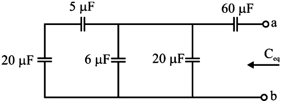
Ques.44. Find the equivalent capacitance, Ceq, at the terminals a-b of the circuit
20 µF
85 µF
80 µF
46 µF
Answer.1. 20 µF
Explanation:-
As shown in the figure the capacitor 5 µF and 20 µF are connected in series therefore its equivalent capacitance
= (5 × 20)/(5 + 20) = 4µF
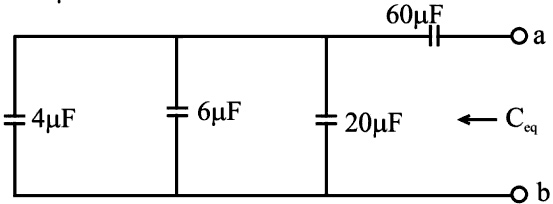
Now capacitance 4µF, 6µF & 20 µF are connected in parallel
= 4 + 6 + 20 = 30 µF
At last 30 µF and 60 µF capacitors is connected in series
Ceq = (30 × 60)/(30 + 60) = 20 µF
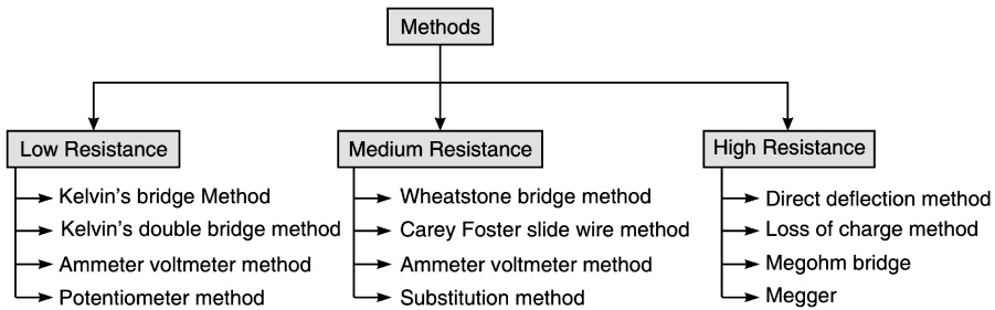
Ques.45. Kelvin double bridge is best suited for the measurement of
Low resistance
Capacitance
Inductance
High resistance
Answer.1. Low resistance
Explanation:-
The resistance with values less than or equal to 1Ω is called low resistance. Example: Armature winding of machines, cables, and ammeter shunts have a low resistance value.
Kelvin double bridge is best suited for the measurement of resistances of very low value.
Ques.46. The time constant of the causal system represented by G(S) = 1/(s + 5) is
10/π seconds
5 seconds
0.2 seconds
π/10 seconds
Answer.3. 0.2 second
Explanation:-
Given time Constant of casual system
G(S) = 1/(s + 5)
or
G(S) = 1/5(1 + 0.2s)
Comparing the above equation with the standard time constant system i.e.
G(S) = 1/(1 + τs)
τ = 0.2 sec
Ques.47. The equation [katex]{e_f} = – \dfrac{{d\phi }}{{dt}}[/katex] where ef is the emf and φ is the flux linkage in a single-turn coil, can best represent
Faraday’s Law
Faraday’s Law and Lenz Law
Lenz Law and Biot-Savart Law
Biot-Savart Law
Answer.2. Faraday’s and Lenz’s laws
Explanation:-
Faraday’s 1st laws of electromagnetic induction tell us about the condition under which an e.m.f. is induced in a conductor or coil when the magnetic flux linking a conductor or coil changes.
Faraday’s 2nd laws of electromagnetic induction give the magnitude of the induced e.m.f in a conductor or coil and may be stated as:
The magnitude of the e.mf induced in a conductor or coil is directly proportional to the rate of change of magnetic flux linkages.
Suppose a coil has N turns and magnetic flux linking the coil increases (i.e. changes) from φ1 Wb to φ2 Wb in t seconds. Now, magnetic flux linkages mean the product of magnetic flux and the number of turns of the coil.
N = e dφ/dt
Lenz Law:- Lenz’s law states: the direction of the induced e.m.f. is such as to oppose the change producing it. Therefore, the magnitude and direction of induced e.m.f. should be written as :
N = −e dφ/dt
Ques.48. A linear time-invariant system, initially at rest, when subjected to a unit step input at t = 0, gives a response y(t)=te−t for t ≥ 0. The transfer function of the system is
1/S2
1/(S + 1)2
S/(S + 1)2
1/S(S + 1)2
Answer.3. S/(S + 1)2
Explanation:-
To get the transfer function from step response we need to get the impulse response of the system.
That is, the impulse response h(t) of a system is equal to the derivative of its step response s(t). Therefore, the impulse response of a system can be determined from its step response simply through differentiation.
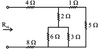
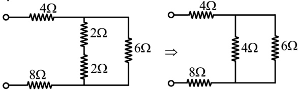
Ques.49. Find the equivalent resistance, Req looking into the terminals of the following circuit as Indicated
14.4 Ω
12.4 Ω
15.2 Ω
10 Ω
Answer.1. 14.4Ω
Explanation:-
From the given figure resistance 6Ω & 3Ω are connected in parallel
= (6 × 3)/(6 + 3) = 2 Ω
Resistance 5Ω & 1Ω are connected in series
5Ω + 1Ω = 6Ω
Now resistance 2 Ω & 2 Ω are connected in series
= 2 + 2 =4Ω
Now resistance 4Ω and 6Ω are connected in parallel
= (4 × 6)/(4 + 6) = 2.4 Ω
Finally resistance 4Ω, 2.4Ω & 8Ω are connected in series
Req = 4 + 2.4 + 8
Req = 14.4Ω
Ques.50. For an ideal single-phase transformer with a primary-to-secondary turns ratio of N:1, the ratio of instantaneous input power to instantaneous output power is