SSC JE 3-Phase Induction Motor Solved Question (2018-2009)
Ques.1. The difference between the stator synchronous speed and rotor speed is called (SSC-2018 Set-1)
- Leading speed
- Lagging speed
- Slip Speed
- Slow Speed
Answer.3. Slip Speed Explanation:- The Slip Speed is defined as the difference between the stator synchronous speed and the Rotor speed of an induction motor. Slip speed = Ns − Nr
Ques.2. In three phase induction motor maximum torque is Inversely Proportional to the (SSC-2018 Set-1)
- Stator Voltage
- Speed of Rotor
- Rotor Reactance
- Decreasing Slip speed
Answer.3. Rotor Reactance Explanation:- The torque of rotor under running condition is [latex]\begin{array}{l}T = \dfrac{{K{\rm{ s}}{E_2}^2{\rm{ }}{R_2}}}{{{R_2}^2 + {{\left( {s{X_2}} \right)}^2}}}\\\\{\text{Slip Corresponding to Max torque}}\\\\s = \dfrac{{{R_2}}}{{{X_2}}}\\\\{\text{Putting the value of slip in above equation we get}}\\\\T = \dfrac{{K{\rm{ }}{R_2}/{X_2}{E_2}^2{\rm{ }}}}{{{R_2}^2 + \left( {{R_2}^2/{X_2}^2} \right).{X_2}^2}} = K\dfrac{{{E_2}^2}}{{2{X_2}}}\end{array}[/latex] Hence it can be concluded that the maximum torque 3 phase induction motor is inversely proportional to the rotor reactance. The maximum torque is not dependent on the rotor resistance R2. But the slip at which it occurs i.e. the speed at which it occurs depends on the value of rotor resistance R2.
Ques.3. No-Load test on an induction motor is conducted to find which of the following losses? (SSC-2018 Set-2)
- Stator core loss
- Rotational Loss
- Stator Copper loss
- All of the above
Answer.4. All of the above Explanation:- No-load test or open-circuit test Without connecting any load on the motor shaft, full voltage is applied across the winding terminals. Since the output of the motor at no-load is zero, the whole of the input power is wasted as various losses. At no-load, the speed of the rotor is very nearly equal to synchronous speed. The emf induced in the rotor and the rotor current is negligibly small. The rotor can, therefore, be approximately considered as an open circuit. The no-load test of an induction motor is, therefore, similar to the no-load test on a transformer. The losses at no-load are: (a) Copper loss I2R loss in the stator winding; (b) Core losses in the stator and rotor (c) Friction and windage losses. At no load, the rotor current is only the very small value needed to produce sufficient torque to overcome the friction and windage losses associated with rotation. The no-load rotor I2R loss is, therefore, negligibly small. Unlike the continuous magnetic core in a transformer, the magnetizing path in an induction motor includes an air gap which significantly increases the required exciting current. Thus, in contrast to the case of a transformer, whose no-load primary I2R loss is negligible, the no-load stator I2R loss of an induction motor may be appreciable because of this larger exciting current. From the total input at no-load, the I2R -loss in the stator winding can be subtracted to get core lost plus friction and windage losses. These losses at no-load are nearly the same as would occur under the full-load condition. This is because core loss depends on applied voltage whereas friction and windage losses depend upon the speed of rotation of the rotor. The applied voltage is assumed to be constant and the variation of the speed of an induction motor from no-load to full-load is negligibly small. The connection diagram of the No-Load test is given below Summary:-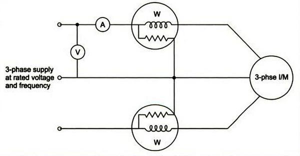
Ques.4. If the torque of the induction motor decreases the__________ (SSC-2018 Set-2)
- Speed of the rotor Increases
- Speed of the Rotor Decreases
- The current of the Rotor Decreases
- Power of the Motor Increases
Answer.1. Speed of the rotor Increases Explanation:- For constant power output in an induction motor Power = Torque × speed or Torque = Power/Speed So if the Torque is decreased the speed of the Rotor is increased. As the rotor speed increases, the frequency of the induced voltage will decrease just as it does in the squirrel-cage motor. The reduction in frequency causes the rotor circuit to become more resistive and less inductive, decreasing the phase angle between induced voltage and rotor current. When current flows through the rotor, a magnetic field is produced. This magnetic field is attracted to the rotating magnetic field of the stator. As the rotor speed increases, the induced voltage decreases because of less cutting action between the rotor windings and the rotating magnetic field also T ∝ V2 this produces less current flow in the rotor and, therefore, less torque. If the rotor circuit resistance is reduced, more current can flow, which will increase motor torque, and the rotor will increase in speed. This action continues until all external resistance has been removed from the rotor circuit by shorting the M-leads together and the motor is operating at maximum speed. At this point, the wound-rotor motor is operating in the same manner as a squirrel-cage motor.
Ques.5. Find the number of poles required, if the frequency is 50Hz and speed of the motor is 500 rpm. (SSC-2018 Set-3)
- 24 Poles
- 12 poles
- 5 Poles
- 10 Poles
Answer.2. 12 poles Explanation:- The synchronous speed of the Motor is given as Ns = 120f/P 500 = 120 × 50/P P = 12 Poles
Ques.6. In squirrel cage induction, the rotor slots are slightly skewed in order to reduce (SSC-2018 Set-3)
- Windage Loss
- Eddy current Loss
- Reduce Magnetic humming
- Friction losses
Answer.3. Reduce Magnetic humming Explanation:- There are two primary sources of noise in polyphase induction motors: magnetically induced noise, called Magnetic noised and noise Induced by the flow of air, called Windage noised. The level of noise of magnetic origin is variable because it depends on the design, the load, the speed, and the power supply. For low-speed machines, magnetic noise is almost always prevailing. It is generated by electromagnetic forces, which occur between the stator and the rotor. They produce vibrations of the machine, mainly the stator. When the frequencies of the electromagnetic forces are close to the resonance frequencies of the stator, the vibrations and the noise are amplified. The magnetic noise of rotating machines can easily be distinguished from other noises by cutting off the electric supply: the magnetic noise is immediately stopped while aerodynamic and mechanical noises decrease slowly with the speed. Rotor conductors are skewed because of these following main reasons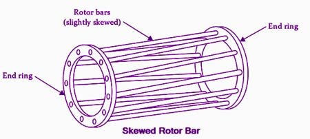
Ques.7. Low-frequency supply is obtained by (SSC-2018 Set-3)
- Motor-generator set
- Frequency changer
- Either Motor-generator set or Frequency changer
- Both Motor-generator set or Frequency changer
Answer.3. Either Motor-generator set or Frequency changer Explanation:- Frequency converter In general, a frequency changer (or converter) is defined as “a machine which converts the power of an a-c system from one frequency to another, with or without change in the number of phases, or in the voltage.” Change d frequency from one value to another, generally from a lower to a higher value, can also be accomplished by taking advantage of the fact that the rotor winding of an induction machine develops emf and current having a frequency which differs from the line frequency by an amount depending upon the slip. In this case, the primary and secondary circuits, carrying of different frequencies, are linked together by a common magnetic field, A conventional wound-rotor motor along with a squirrel cage induction motor may be used as a frequency converter to generate a frequency different from that of the utility company. The stator of the wound-rotor machine is connected to the utility line, and the rotor is driven at an appropriate speed by a motor M i.e Squirrel Cage Induction motor. The rotor supplies power to the 3-phase load at a voltage E2 and frequency f2 both of which depend upon the slip. f′=sf where f′ is rotor frequency, f is stator frequency s is slip. In motoring, mode slip lies between 0 and 1. So, rotor frequency maybe 0, less than stator frequency or equal to stator frequency. In generating mode slip s lies between -1 and 0. So, rotor frequency can’t be greater than stator frequency here too. So, it is clear that when slip s>1, only then f′ > f. Thus in Braking or plugging mode, the rotor frequency can be greater than stator cause slip s > 1 here only. In general, the desired frequency is two or three times that of the utility company. According to the above equation in order to attain this frequency, the slip must be positive and greater than 1. As a result, the shaft must be rotated against the direction of the revolving flux. The operation of the frequency converter is then identical to that of an induction motor operating as a brake. However, the power P usually dissipated as heat in the rotor is now available to supply power to the load. The converter acts as a generator.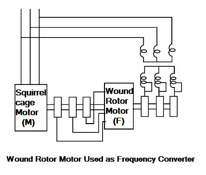
Ques.8. What type of operate a direct-on-line starter consists of a coil operated (SSC-2018 Set-3)
- Capacitor operated
- A coil Operated
- Eddy current Operated
- Resistor Operated
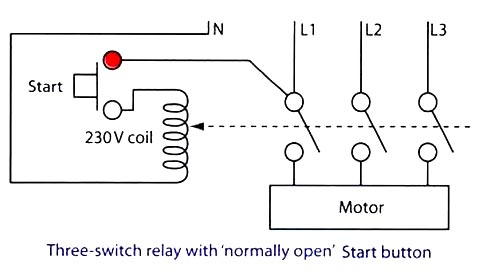
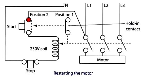
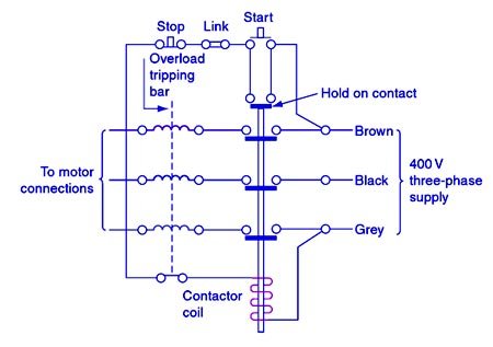
Answer.2. A coil Operated Explanation:- Direct-On-Line (DOL) starter is the simplest and cheapest coil operated starting method of squirrel-cage (induction) motors. The expression ‘Direct-On-Line’ starting means that the full supply voltage is directly connected to the stator of the motor by means of a contactor starter. Since the motor is at a standstill when the supply is first switched on, the initial starting current is heavy. This ‘inrush’ of current can be as high as 6 to 10 times the full load current, i.e. a motor rated at 10A could have a starting current inrush as high as 60A, and the initial starting torque can be about 150 percent of the full-load torque. Thus you may observe motors ‘jumping on starting if their mountings are not secure. As a result, Direct-On-Line starting is usually restricted to comparatively small motors with outputs of up to about 5 kW. DOL starters should also incorporate a means of overload protection, which can be operated by either magnetic or thermal overload trips. These activate when there is a sustained increase in current flow. To reverse the motor you need to interchange any two of the incoming three-phase supply leads. If a further two leads are interchanged then the motor will rotate in the original direction. As soon as we put a supply onto the coil it energizes, it creates a magnetic field. Everything in the magnetic field will be pulled in, therefore, the strip will be pulled onto the contacts. As long as the coil remains energized and is a magnet, Strip remains in contact. Obviously, this would be no good for our starter, as every time the power is put on, the starts will become active and start operating whatever is connected to it. In the case of machinery, this could be very dangerous. The starter design, therefore, goes one step further to include no-volts protection. The simple addition of a ‘normally open‘ Start button gives this facility, as shown in Figure Our next problem though is that every time we take our finger off the Start button, the button springs back out, the supply to the coil is lost and the motor stops. This is the ‘no-volt’ protection element in operation. Basically, No Volt Coil ensures that whenever supply resumes after switching off or supply failure, the motor does not start on its own, but starts only after the user starts it and that too through current limiting resistors. What we need for normal operation is a device called the ‘hold in’ or ‘retaining contact, as shown in Figure. This is a ‘normally closed’ contact (position 1) which is also placed in the magnetic field of the coil. Consequently, when the coil is energized, it is also pulled in the direction shown, and in this case, across and onto the terminals of the Start button (position 2). We can now take our finger off the Start button, as the supply will continue to feed the coil by running through the ‘hold in’ contact that is linking out the Start button terminals (position 2). This now means that we can only break the coil supply and stop the motor by fitting a Stop button. In the case of starters fitted with a 230 V coil, this will be a normally closed button placed in the neutral wire. Now, for the fraction of a second that we push the Stop button, the supply to the coil is broken. the coil ceases to be a magnet and the ‘hold in’ contact returns to its original position (position 1). Since the Start button had already returned to its original open position when we released it, when we take our finger off the Stop button everything will be as we first started. Therefore any loss of supply will immediately break the supply to the coil and stop the motor: if a supply failure was restored, the equipment could not restart itself – someone would have to make the conscious decision to do so. When the start button is pressed, the current will flow from the brown phase through the control circuit and contactor coil to the grey phase which energizes the contactor coil and the contacts closes, connecting the three-phase supply to the motor, as shown in Fig. If the start button is released the control circuit is maintained by the hold on contact. If the stop button is pressed or the overload coils operate, the control circuit is broken and the contactor drops out, breaking the supply to the load. Once the supply is interrupted, the supply to the motor can only be reconnected by pressing the start button. Therefore, this type of arrangement also provides no-volt protection. When large industrial motors have to be started, a way of reducing the excessive starting currents must be found. One method is to connect the motor to a star-delta motor starter.Direct-On-Line (DOL) starter
Connection Of direct On-Line starter
Working of Direct-on-Line Starter
Ques.9. Rotating magnetic fields are also used in 3-phase induction motors rotor developing (SSC-2018 Set-4)
- Eddy current
- Voltage Lag
- Load current
- Phase current
Answer.1. Eddy current Explanation:- The polyphase induction type of motor depends upon the principle of a rotary magnetic field. Polyphase motors using a rotating magnetic field were invented by Nikola Tesla in 1898. When a rotating magnetic field is subjected to a metallic cylinder free to rotate in the field, eddy currents are set up in it. These currents, according to Lenz’s law, try to reduce the relative motion between the cylinder and the field. Therefore the cylinder begins to rotate in the direction of the field. This principle is used in induction motors. Let us explain in detail The rotating magnetic field can be defined as the field or flux having constant amplitude but whose axis is continuously rotating in a plane with a certain speed. So if the arrangement is made to rotate a permanent magnet, then the resulting field is a rotating magnetic field. But in this method, it is necessary to rotate a magnet physically to produce a rotating magnetic field. But in three-phase induction motors, such a rotating magnetic field is produced by supplying currents to a set of stationary windings, with the help of three-phase a.c. supply. The current-carrying windings produce the magnetic field or flux. And due to the interaction of three fluxes produced due to three-phase supply, resultant flux has a constant magnitude and its axis rotating in space, without physically rotating the windings. This type of field is nothing but rotating; magnetic field. A 3-phase induction motor mainly consists of two major parts, the stator and the rotor separated by a uniform air gap. When the 3-phase winding suitably wound on the stator is supplied with 3-phase balanced ac supply, a uniformly rotating magnetic field of constant magnitude and rotating at synchronous speed is produced. The rotor of an induction motor placed in a rotating magnetic field. The speed of this rotating magnetic field is known as the synchronous speed (N,). The lines of force of the stator rotating magnetic field cut the rotor conductors and as a result, an alternating emf is induced in these conductors. Due to the relative motion between the rotating magnetic field and the rotor, a voltage is induced in the conductors placed on the rotor. Since the conductors on the rotor form a closed path due to short-circuited end rings (in cage type of rotor) or through external resistance via slip rings (in case of wound rotor) hence the rotor winding for both types of 3-phase induction motors is equivalent to a short-circuited winding The rotating magnetic field developed by the AC current flowing in the stator windings induces a current in the rotor. Due to this the short-circuited turns of the rotor develop eddy currents in the rotating field of the stator. The interaction of the two magnetic fields turns the rotor and drives the motor shaft firmly attached to the rotor by Lorentz force. It is obvious that the rotor speed cannot become equal to the synchronous speed because, in that case, there will be no relative motion between the rotating magnetic field and the rotor, resulting in no induced current in the rotor conductors, and no torque acting on the rotor. Then, the rotor tends to retard. Therefore, there will always be a slight difference between synchronous speed N1 and the speed of the rotor N2.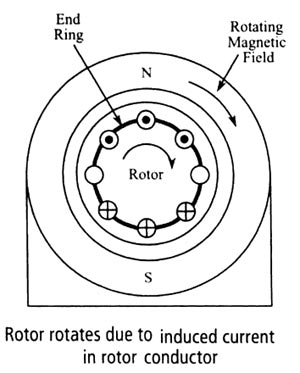
Ques.10. One of the speed control methods of a 3 phase induction motor is (SSC-2018 Set-4)
- V/F control
- Stator current control
- Core loss control
- Eddy current Control
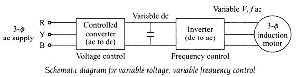
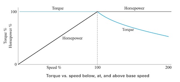
Answer.1. V/F control Explanation:- An induction motor on a normal supply operates with a rotating field set up by three-phase currents in the stator winding. The magnitude of the field is controlled broadly by the voltage impressed upon the winding by the supply. This is because the resistance of the winding results in only a small voltage drop, even at full-load current, and therefore in the steady-state, the supply voltage must be balanced by the e.m.f. induced by the rotating field. This e.m.f. depends on the product of three factors: Synchronous speed, therefore, the motor speed can be controlled by varying supply frequency. The voltage induced in the stator is proportional to the product of supply frequency and air-gap flux. If V = φF And also the torque of an induction motor is directly proportional to the flux T ∝ φ ∝ V/F Hence for the same design parameters [φ remaining the same] and ratio V/F, the torque of the motor, T, will remain constant. Since both V and f, are functions of the supply system, a variation in V and f can alter the performance and the speed-torque characteristics of a motor as required, at constant torque. The variable frequency, variable voltage supply required in this method of speed control, can be obtained by using a controlled converter and an inverter in between the 3-phase supply and the 3-phase induction motor, as shown in Fig. The controlled converter, rectifies the 3-phase, ac supply of standard frequency and voltage to a dc of variable voltage. The voltage can be varied, as per the requirement of the frequency variation. The de variable voltage is inverted to 3-phase, AC with variable frequency, variable voltage by a 3-phase inverter. The frequency control is obtained by the inverted. Thus, with the above circuit, it is possible to obtain a variable frequency, the variable voltage source with V/f constant. to be applied to the 3-phase induction motor. Increased Voltage If in the steady-state, the voltage applied to the stator terminals is increased without a corresponding increase in the frequency, only the flux can vary to regain the balance between applied voltage and e.m.f. If the flux is forced to increase by applying excessive voltages, the iron core of the machine is driven progressively into saturation. This not only increases iron losses due to hysteresis and eddy currents but can lead to a very marked increase in stator current, with corresponding resistive losses. Since most machines are designed to work with the minimum of material, their magnetic circuits are normally very close to saturation and excessive stator voltage is a condition that must be carefully avoided. Reduce frequency Any reduction in the supply frequency, without a change in the terminal voltage, causes u increase in the air-gap flux. Induction motors are designed to operate at the Knee point of the magnetization characteristic to make full use of the magnetic material. Therefore, the increase in flux will saturate the motor. This will increase the magnetizing current, distort the line current and voltage, increase the core loss and the stator copper low, and produce a high-pitch acoustic noise. Base Speed Base speed,” is defined as the speed at which the motor will first produce its maximum designed power output, and “maximum speed,” the fastest the motor can spin while producing that same amount of power (available torque falls off as speed increases past “base speed.”) Operation above base speed First, operation above base speed is easily achieved by increasing the output frequency above the normal mains frequency since the rise in the applied voltage which is not permissible beyond the rated voltage, and which has already been attained by reaching the rated speed. The speed beyond the rated is therefore obtained by raising the supply frequency alone and maintaining the voltage at constant as it rated value. Since V is constant above base speed, the flux will fall as the frequency is increased after the output voltage limit is reached. The machine flux falls in direct proportion to the actual V/f ratio. Although this greatly reduces the core losses, the ability of the machine to produce torque is impaired and the less mechanical load is needed to draw full-load current from the inverter. The drive is said to have a constant power characteristic above base speed. Many applications not requiring full torque at high speeds can make use of this extended speed range. Operation below base speed Each AC induction motor is designed to run at a particular RPM, called base speed. When power is applied, the motor accelerates from 0 RPM. As it does, the torque remains constant and the horsepower increases until the base speed is reached. Above base speed, the torque falls off while the horsepower remains constant. Below the base speed (V/F ratio is maintained constant, except at low frequencies where (V/f ) ratio is increased to keep maximum torque constant. By maintaining a constant ratio of voltage to speed, we can maintain a constant air gap flux. Because torque is proportional to air gap flux, hence by constant V/f ratio, the torque can be made independent of speed in an AC motor. Hence we can achieve constant torque down to very low speeds. Example One example is paper winder. When it begins to wind, the empty core is light and does not require much torque to turn. Therefore, it can be turned above base speed at reduced torque. As the roll is being wound and becomes heavier, the torque required to turn it becomes greater. Therefore, it is necessary for the drive to slow the speed and eventually run below the base speed so that torque is increased to handle the load. Eventually, the roll is heavy and requires the motor to provide maximum torque.
stator drop is neglected, the terminal voltage can be considered proportional to the product of
frequency and flux.
and φ = V/F