Ques.11. A 12 kΩ resistor is in series with a 90 mH coil across an 8 kHz ac source. The current flow in the circuit, expressed in polar form, is I = 0.3 ∠0° mA. The source voltage, expressed in polar form, is
Ques.12. A 20-H coil is connected across a 110-V 60-Hz power line. If the coil has zero resistance, What will be the value of the power drawn in the circuit.
0 W
10 W
5 W
2 W
Answer.1. 0 W
Explanation:-
Inductive reactance XL = 2πfL
XL = 6.28 × 60 × 20
XL = 7536Ω
Current Drawn IL = VL/XL
IL =110/7536 = 14.6 mA
Active power P = V.I.Cosφ
Since the resistance is zero the circuit is purely inductive in nature and phase angle φ = 90°
110(14.6 × 10⁻³ ) (cos90°)
P = 0 Watt
Ques.13. A 1.2 kΩ resistor is in series with a 15 mH coil across a 10 kHz ac source. The magnitude of the total impedance is
152.6 Ω
1.526 Ω
15.26 Ω
1526 Ω
Answer.4. 1526 Ω
Explanation:-
Inductive reactance XL = 2πfL
XL = 6.28 × 10 × 15
XL = 0.942 kΩ
Impedance Z
$\begin{array}{l} Z = \sqrt {{R^2} + {X^2}_L} \\ \\ Z = \sqrt {{{(1.2)}^2} + {{(0.942)}^2}} \end{array}$
Z = 1.526 kΩ
Z = 1526 Ω
Ques.14. Which of the following power factors results in less energy loss in an RL circuit?
0.2
0.6
0.1
0.9
Answer.3. 0.1
Explanation:-
The power factor is the ratio of the actual power being consumed by an appliance to the apparent power it draws from the source.
In the case of a pure resistive circuit, the power factor is 1, and the current and voltage are in the same phase. Also in the pure resistive circuit, the component is dissipating as much power (real power) as it is drawing from the source (apparent power).
So from the above discussion, it is clear that
Power factor ∝ Energy dissipation or Energy losses.
Hence the minimum energy loss will occur when the power factor is 0.1.
Ques.15. A 470 Ω resistor and a 200 mH coil are in parallel. Both components are across a 1.5 kHz ac source. The total admittance of the circuit, in polar form, is
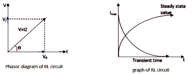
Ques.16. To increase the current in a series RL circuit, the frequency should be
Increase
Decrease
Remain Same
Any of the above
Answer.2. Decrease
Explanation:-
The resistor and the inductor always share the input voltage. Thus, the resistor too may absorb a part of the input voltage in the circuit. Therefore, the voltage available to the inductor during this interval can only be less than what is available in the source.
As the resistor voltage tends to increase in the RL circuit the inductor voltages decrease therefore the current increases as shown in the graph.
When the inductor voltage becomes zero then the voltage source output will be across the resistor, and the current will be at its maximum value.
Inductive reactance XL = 2πfL
Hence from the above equation, the inductive reactance is directly proportional to the frequency hence to increase the current we need to decrease the frequency so that the circuit becomes more resistive in nature.
Ques.17. In a series RL circuit, 12 V RMS is measured across the resistor, and 14 V RMS is measured across the inductor. The peak value of the source voltage is
Ques.19. A 470 Ω resistor and a coil with 125 Ω inductive reactance are in parallel. Both components are across a 15 V ac voltage source. Current through the inductor is
40 mA
120 mA
60 mA
3o mA
Answer.2. 120 mA
Explanation:-
Since the voltage source is parallel to both resistances.
So, In parallel circuit V1 = V2 = V3 = V
Current in inductor, I = V/XL =15/125 = 120 mA
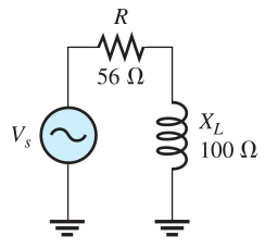
Ques.20. For the circuit given below find the phasor expression for the impedance in both rectangular and polar forms.