Ques.31. The total current in the Parallel RL circuit is expressed as
It = IR − IjL
It = IR + IjL
IR = It + IjL
None of the above
Answer.1. It = IR − IjL
Explanation:-
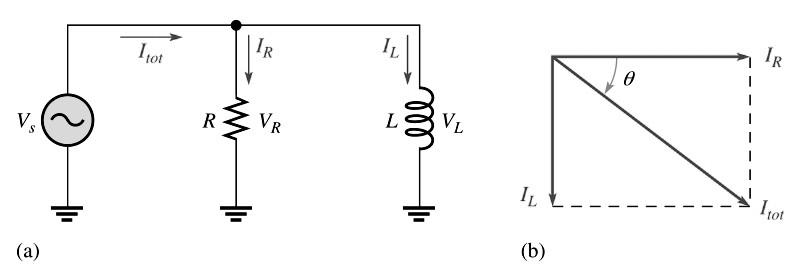
Phase Relationships of Currents and Voltages for parallel RL circuit
Figure (a) shows all the currents in a basic parallel RL circuit. The total current It divides at the junction into the two branch currents, IR and IL. The applied voltage Vs appear across both the resistive and the inductive branches, so Vs, Vr, and VL are all in phase and of the same magnitude.
The current through the resistor is in phase with the voltage. The current through the inductor lags the voltage and the resistor current by 90°. By Kirchhoff’s current law, the total current is the phasor sum of the two branch currents, as shown by the phasor diagram in Figure (b). The total current is expressed as
It = IR − IjL
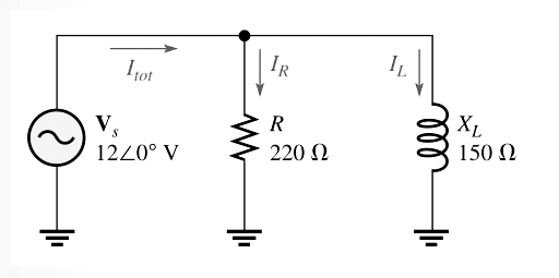
Ques.32. Find the total current in the Parallel RL circuit shown in the figure below
54.5 A − j80 A
80 mA − 54.5 mA
54.5 mA + j80 mA
54.5 mA − j80 mA
Answer.4. 54.5 mA − j80 mA
Explanation:-
From the given figure the resistor current, the inductor current, and the total current are
IR = Vs/R = 12∠0°/220∠0° = 54.5∠0° mA
IL = Vs/XL = 12∠0°/150∠90° = 80∠−90° mA
It = IR − IjL
It = 54.5 mA − j80 mA
Ques.33. In a purely inductive ac circuit, all of the energy delivered by the source is stored by the ______
Resistor
Inductor
Resistor and Inductor
Any of the above
Answer.2. Inductor
Explanation:-
In a purely inductive ac circuit, all of the energy delivered by the source is stored by the inductor in its magnetic field during a portion of the voltage cycle and then returned to the source during another portion of the cycle so that there is no net energy conversion to heat.
Ques.34. When the resistance in a series RL circuit is _____ the inductive reactance, more of the total energy delivered by the source is converted to heat
Smaller than
Equal to
Twice
Greater than
Answer.4. Greater than
Explanation:-
When the resistance in a series RL circuit is greater than the inductive reactance, more of the total energy delivered by the source is converted to heat by the resistance than is stored by the inductor. Likewise, when the reactance is greater than the resistance, more of the total energy is stored and returned than is converted to heat.
Ques.35. The power of the inductive RL circuit is expressed as
P = I2RL
P = I/XL
P = I XL
P = I2 XL
Answer.4. P = I2 XL
Explanation:-
The power dissipation in resistance is called the true power. The power in an inductor is reactive power and is expressed as
P = I2 XL
Ques.36. A smaller power factor indicates _____ true power and ____ reactive power.
More, More
Less, More
Less, More
More, Less
Answer.2. Less, More
Explanation:-
The power factor equals the cosine of θ (PF = Cosθ).
As the phase angle between the applied voltage and the total current increases, the power factor decreases, indicating an increasingly reactive circuit. A smaller power factor indicates less true power and more reactive power.
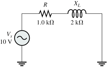
Ques.37. Determine the Power factor of the given RL circuit when the resistance is 1.0 kΩ, inductive reactance XL is 2.0 kΩ and the supply voltage is 10 V as shown in the figure.
The phase angle indicated in the expression for Z, is
θ = 63.4°
The power factor is, therefore,
PF = cosθ = cos(63.4°) = 0.448
Ques.38. When the power factor is _____, all of the current to a load is 90° out of phase with the voltage.
Unity
Leading
Zero
None of the above
Answer.3. Zero
Explanation:-
When the power factor is zero, all of the current to a load is 90° out of phase with the voltage (reactive).
Ques.39. For power factor correction the capacitor is connected in ______
Series
Series and Parallel
Parallel
None of the above
Answer.3. Parallel
Explanation:-
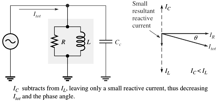
If the load consists of a series connection of a resistor with resistance R and an inductor with inductance L adding a parallel capacitor with capacitance value C can increase the power factor to the desired value. The power factor of an inductive load can be increased by the addition of a capacitor in parallel, as shown in Figure. The capacitor compensates for the phase lag of the total current by creating a capacitive component of current that is 180° out of phase with the inductive component. This has a canceling effect and reduces the phase angle and the total current and increases the power factor, as illustrated in the figure.
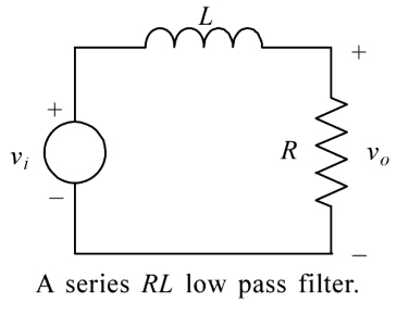
Ques.40. In low pass RL filter, the Resistance and Inductance are connected in
Series
Parallel
Series-Parallel
None of the above
Answer.1. Series
Explanation:-
The basic function of a low pass filter is to pass low frequencies with very little loss and to attenuate high frequencies. A familiar application of low pass filters is in the tone control of hi-fi amplifiers. The treble control varies the cut-off frequency of an LP filter and is used to attenuate the high-frequency noise.
Two circuits that behave as low pass filters are the series RL circuit and the series RC circuit.