
Ques 41. A shaded pole motor does not possess
- Commutator
- Centrifugal switch
- Capacitor
- All of the above
Explanation:
SHADED-POLE MOTORS
The shaded-pole motor has the lowest starting torque of all the single-phase motors. It is relatively inexpensive and is used to turn very small fan blades connected directly to the shaft of the motor. The basic construction of this motor is very simple since no start winding is present. The imbalance in the magnetic field needed to produce rotation is obtained by shading a portion of the run winding with heavy copper wire or band.

When the motor is energized, the strength of the magnetic field is different in the area of the main poles than in the area of the shaded poles, allowing the rotor to turn.
Note:-
- A shaded pole motor does not have the starting winding, therefore there is no need of the centrifugal switch.
- The capacitor is not used in the shaded pole because phase shift is produced by the method of induction.
- Commutators are used in direct current (DC) machines: dynamos (DC generators) and many DC motors, as well as universal motors and a shaded-pole motor, is the original type of AC single-phase induction motor, therefore there is no need for commutation.
Ques 42. The locked rotor current of a shaded pole motor is
- Less than full load current
- Equal to full load current
- Slightly more than full load current
- None of the above
Explanation:
Locked rotor current is basically the current drawn by the motor at its rated voltage when its rotor is kept stationary or in other words rotor is not spinning or rotating. So when we start a motor, its rotor is already at rest. This means, starting current and locked rotor current should be the same. Under this condition, the rotor winding cut the rotating flux without rotating which is equivalent to the short circuit of a transformer secondary.
In the shaded pole motor, its stalled locked rotor current is slightly more than the rated current so that it can even remain stalled or stand still for short period without any harm.
Ques 43. If a D.C. series motor is operated on an A.C. supply, it will have
- Poor power factor
- Poor efficiency
- Spark excessively
- All of the above
Explanation:
- It depends on the construction of the motor if the armature winding is connected in series it will behave as a universal motor and we know that a universal motor can work on both AC and DC motors.
- If the armature winding is connected in parallel there won’t be a unidirectional magnetic field, the direction of the magnetic field, as well as the direction of the current in the armature, will be reversed in the second half of the AC cycle as a result, the motor either run slowly or won’t rotate.
- When an AC supply is given to the DC series motor then there will be high inductance in field and armature circuits which causes a low power factor.
- With operation on alternating currents, the eddy current loss increases considerably. Hence in addition to the armature, the field structure has to be laminated.
- The D.C. series motor when connected to A.C. supply has a much greater tendency to produce sparking. Also, its power factor is very low which will lead to poor efficiency of the motor.
- Both excessive sparking and poor factor are prevented by compensating the motor, the aim of which is to neutralize the effect of self-induction. The armature is compensated by employing coils carrying the armature current and placed in such a way as to neutralize the armature flux. The compensating coil can be connected in series with the main field or can be short-circuited on itself.
Ques 44. The capacitors used in single-phase capacitor motors have no
- Polarity Marking
- Voltage Rating
- Dielectric medium
- None of the above
Explanation:
In single-phase electric induction motors generally two separate sets of windings are used, Viz. main and auxiliary winding. A capacitor is used in series with auxiliary winding to create a phase difference between the currents of the two windings. This in turn creates a rotating magnetic held around the rotor, making it rotate.
Some motors use high-value capacitors in auxiliary windings only during the starting, which are disconnected through a centrifugal switch once the motor attains the required speed. These are mostly of electrolytic type and are called motor start capacitors. Capacitor-start capacitor-run motors are also commonly employed.
There are generally three different reasons why a capacitor is used with a ceiling fan or motor:
(a) The capacitor is used to give a phase shift and create a rotating magnetic field, so the motor will start turning more easily, against the inertia of the blades or load.
(b) It is sometimes used in speed control circuitry.
(c) The capacitor may be used for power factor correction.
(d) A capacitor-start induction motor has a non-polarized electrolytic capacitor in series with the auxiliary winding during starting, which is disconnected once the motor starts.
(e) A capacitor-start capacitor-run motor typically has a large non-polarized electrolytic capacitor in series with the auxiliary winding for starting, then a smaller non-electrolytic capacitor during running. An electrolytic capacitor has no polarity marking.
Ques 45. In the case of a reluctance motor, when the load is increased so that it cannot maintain synchronous speed the motor will
- Become unstable
- Run as an induction motor
- Burn out
- None of the above
Explanation:
Reluctance Motor
The three-phase as well as single-phase motors can be built with rotors without DC excitation but having non-uniform air-gap reluctance. The stator construction of such motors is similar to 3-phase or 1-phase induction motors but the shape of the squirrel cage rotor of these motors is changed such that it has variable magnetic reluctance along the air gap. The 3-phase induction motors with such rotors are usually called synchronous induction motors. However, the single-phase induction motors built with a variable air-gap reluctance rotor without DC excitation are called reluctance motors.
Working of reluctance motor
- When supply is given to the stator of a single-phase (split-phase) reluctance motor, a revolving field is set up in the stator.
- The rotor starts rotating as an induction motor rotor and picks up the speed near to synchronous speed.
- Then the rotor is pulled into synchronous speed with the stator field since reluctance torque is developed at the salient poles which have smaller air-gap reluctance.
- Thus, the rotor starts rotating at synchronous speed once the reluctance torque is developed.
- If it is loaded beyond the value of synchronous pull-out torque, it will continue to operate as a single-phase induction motor up to over 500 percent of its rated torque.
- If the load is increased beyond the given value then the reluctance motor becomes out of synchronism.
- The speed is dropped to a value where slip is sufficient to develop necessary torque to drive the load and at that condition, the reluctance motor runs as an induction motor.
Ques 46. Which of the following motors are preferred for tape recorders?
- Capacitor start motor
- Capacitor run motor
- Hysteresis motor
- None of the above
Explanation:
A hysteresis motor is a single-phase cylindrical (non-salient pole type) synchronous induction motor. The amount of torque produced as a result of rotor magnetization is not as great as reluctance torque. But hysteresis torque is extremely steady in both amplitude and phase in spite of fluctuations in supply voltage. As a result of this, these motors are extremely popular in driving high-quality cassette players, compact disc players, record players, tape recorders, clocks, etc.
Ques 47. In a shaded pole single-phase motor, the revolving field is produced by the use of
- Shading coils
- Capacitor
- Inductor
- All of the above
Explanation:
SHADED-POLE MOTORS
- A shaded-pole motor employs a salient-pole stator and a cage rotor.
- The projecting poles on the stator resemble those of DC machines except that the entire magnetic circuit is laminated and a portion of each pole is split to accommodate a short-circuited coil called a shading coil.
- The coil is usually a single band or strap of copper. The effect of the coil is to produce a small sweeping motion (revolving field) of the field flux from one side of the pole piece to the other as the field pulsates.
- This slight shift in the magnetic field produces a small starting torque.
- Thus, shaded-pole motors are self-starting.
The shaded-pole motor has the lowest starting torque of all the single-phase motors. It is relatively inexpensive and is used to turn very small fan blades connected directly to the shaft of the motor. The basic construction of this motor is very simple since no start winding is present. The imbalance in the magnetic field needed to produce rotation is obtained by shading a portion of the run winding with heavy copper wire or band.
When the motor is energized, the strength of the magnetic field is different in the area of the main poles than in the area of the shaded poles, allowing the rotor to turn.
Ques 48. The power factor of a single-phase induction motor is usually
- Always Lagging
- Always Leading
- Unity
- None of the above
Explanation:
- In order to self-start a single-phase induction motor one must create a rotating magnetic field on the stator. Therefore split phase motor has two winding one is starting winding and the other is main winding or running winding.
- The starting winding has fewer turns and a small diameter, therefore, it has high resistance and low inductance.
- The running winding has a heavier wire of more turns, therefore, it has low resistance and high inductance.
- As we know that for high inductance current lags behind voltage by a large angle and for high resistance, the current is almost in phase with the voltage.
- Hence, an induction motor has a lagging power factor since it withdraws reactive power from the Source to meet its magnetizing requirements. For the loading conditions, the power factor is 0.6 – 0.8 lagging. For the unloading condition, the power factor is 0.2-0.3 lagging.
- Single-phase motors hardly work with an efficiency of 55 to 60 %.
Ques 49. When a D.C. series motor is connected to A.C. supply, the power factor will be low because of
- The fine copper wire winding
- The induced current in rotor due to variations of flux
- High inductance of field and armature circuits
- None of the above
Explanation:
- It depends on the construction of the motor if the armature winding is connected in series it will behave as a universal motor and we know that a universal motor can work on both AC and DC motors.
- If the armature winding is connected in parallel there won’t be a unidirectional magnetic field, the direction of the magnetic field, as well as the direction of the current in the armature, will be reversed in the second half of the AC cycle as a result, the motor either run slowly or won’t rotate.
- When an AC supply is given to the DC series motor then there will be high inductance in field and armature circuits which causes a low power factor.
- With operation on alternating currents, the eddy current loss increases considerably. Hence in addition to the armature, the field structure has to be laminated.
- The D.C. series motor when connected to A.C. supply has a much greater tendency to produce sparking. Also, its power factor is very low which will lead to poor efficiency of the motor.
- Both excessive sparking and poor factor are prevented by compensating the motor, the aim of which is to neutralize the effect of self-induction. The armature is compensated by employing coils carrying the armature current and placed in such a way as to neutralize the armature flux. The compensating coil can be connected in series with the main field or can be short-circuited on itself.
Ques 50. The speed/load characteristics of a universal motor is same as that of
- D.C. series motor
- D.C. shunt motor
- A.C. motor
- None of the above
Explanation:
A universal motor is usually categorized as an AC motor. It gets its name from its ability to operate on either AC or DC voltage. Its construction is very similar to a series-wound DC motor.
Characteristics of Universal Motor
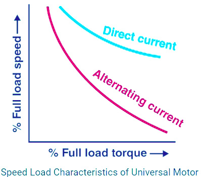
The speed/load characteristics of a universal motor is same as that of D.C series motor. The speed of a universal motor is inversely proportional to the load, i.e., the speed is low at full load and it is high on no load. The speed may become dangerously high at no load due to low field flux. Therefore, to avoid its operation at no load, normally these motors are connected with permanent loads. The figure shows the typical torque-speed characteristics of this motor for both ac and dc operations. In actual practice, it will likely be found that the universal motor is not as effective on DC as a series motor designed for DC operation.
Since the universal motor is a series-wound, it has performance characteristics similar to a DC motor.
- It has high starting torque.
- The no-load speed is very high, but not high enough to break apart.
- It has poor speed regulation when the load to which it is connected changes.
- To minimize the effect of the load, most universal motors are designed to overcome this by operating at a very high speed of 3500 RPM or greater.
- In a router application, for example, the universal motor runs at 18,000 RPM.
There are three significant differences between the DC series motor and the universal motor:
- In a DC motor, the iron cores are made of solid iron. The universal motor uses laminated iron to reduce energy loss from excessive heating due to eddy currents that are created from magnetic fields constantly reversing direction.
- In a universal motor, the magnitude of the fields will fluctuate at twice the line frequency (120 times a second). This condition creates a reduction in output torque compared to a DC motor, which has constant field strength. This reduction of output power is partially compensated for by using more armature loops.
- There is an excessive voltage drop across the series field windings of a DC series motor due to the high inductive reactance that develops when an AC voltage is applied. To minimize the voltage drop across the series coil of a universal motor, it is wound with a small number of turns on a low reluctance core.
FOR TRANSMISSION AND DISTRIBUTION SYSTEM MCQ CLICK HERE
FOR DC MOTOR MCQ CLICK HERE
FOR 1-Φ INDUCTION MOTOR MCQ CLICK HERE
FOR 3-Φ INDUCTION MOTOR MCQ CLICK HERE
FOR SYNCHRONOUS GENERATOR OR ALTERNATOR MCQ CLICK HERE
FOR SYNCHRONOUS MOTOR MCQ CLICK HERE
FOR DC MOTOR MCQ CLICK HERE
FOR DC GENERATOR MCQ CLICK HERE
FOR POWER SYSTEM MCQ CLICK HERE
FOR TRANSFORMER MCQ CLICK HERE
FOR BASIC ELECTRICAL MCQ CLICK HERE
FOR CONTROL SYSTEM MCQ CLICK HERE
