Ques 61. Which of the following single-phase motors is available with a speed as low as one revolution per minute?
Shaded✔
Reluctance
Hysteresis
Universal
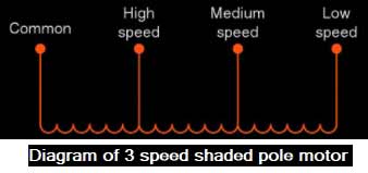
The above figure shows the 3 speed shaded pole motor. The main winding is the speed winding for high-speed operation. For medium-speed operation, the main winding is connected in series with medium-speed winding which increases the number of poles and produces fewer revolutions per minute.
And for further reduction in speed, the main winding is connected in series with medium and low-speed operation thus increasing the number of poles in the stator and reducing speed upto one revolution per minute.
Ques 62. A vacuum cleaner employs ________ motor.
Resistance split phase
Capacitor start
Shaded Pole
Single-phase series✔
To create vacuum high-speed motors are required. Ac series motor are best suited as they can be operated at very high speed
Ques 63. In a capacitor start single phase induction motor, the current in the
Supply lines leads the voltage
Starting winding lags the voltage
Main winding leads the voltage
Starting winding leads the voltage✔
In the capacitor start inductor motor two winding is used, the main winding and the starting winding. With starting winding we connect a capacitor so the current flowing in the capacitor leads the applied voltage by some angle, φst.
Ques 64. In a single-phase induction motor, the speed-sensitive centrifugal switch is connected in ____winding.
Parallel with the main
Series with main
Parallel with starting
Series with starting✔
The centrifugal switch is connected in series with the starting winding. The primary function of the centrifugal switch is to produce rotating flux in conjunction with the main winding at the time of starting.
When the motor has started and reaches nearly 75% of synchronous speed, it produces its own rotating field from the cross-field effect. The starting winding now has no function to perform and is removed from the circuit by a centrifugally operated switch.
Ques 65. At starting, the current through the starting winding (Is ) of single-phase induction motor
Lags V by 90°
Leads V by 90°
Nearly in phase with V✔
Leads V by 75°
In a single-phase induction motor mainly there are two types of windings main winding or running winding and auxiliary winding or starting winding.
The auxiliary winding or running winding carries a series resistance such that its impedance is highly resistive on the other hand the main winding or running winding is highly inductive in nature.
As we know that if the circuit is highly resistive the current and voltage are in phase with each other therefore current through starting winding in single phase induction motor is almost in phase with the voltage.
Ques 66. In a single-phase induction motor at the start, the two revolving fields produce
Unequal torques in the rotor conductors
No torque in the rotor conductor
Equal and opposite torques in the rotor conductors✔
Equal torques in the same direction in the rotor conductors
The working principle of an ac machine is primarily “one field following another field”. In the case of a multiphase induction motor, there will be a virtual rotating magnetic field.
But considering the case of a single-phase induction motor, it’s only a pulsating field that is produced and not a rotating one. This can also be explained on the basis of ‘DOUBLE REVOLVING FIELD THEORY‘, which goes as follows:
Current through a conductor produces a flux. This flux can be resolved into 2 components, each one rotating in the opposite directions at the same speed(slip).
As a result, the net flux is zero, and the induced current in the rotor conductors is zero, resulting in zero torque. So, a single-phase induction motor is not self-starting.
Ques 67. If the synchronous motor can be used as a synchronous condenser when it is
Overexcited✔
Under excited
Overloaded
Under Loaded
When the synchronous motor operates at the leading power factor then Rotor is overexcited in such a way that the back emf (Eb which is generated in the stator due to dc excitation of the rotor ) is greater than the supply voltage (V).
In this case, a Synchronous motor will be operating at a leading power factor. At this time resultant flux is greater than that is required for the unity power factor, then this extra flux will generate reactive power so the motor will generate reactive power. And it will use active power too for mechanical work.
Therefore synchronous motor working on leading PF will work as a synchronous condenser.
Ques 68. Which of the following methods would give a higher than the actual value of regulation of an alternator?
ZPF method
MMF method
EMF method✔
ASA method
Compared to other methods, the value of voltage regulation obtained by the synchronous impedance method (EMF Method) is always higher than the actual value and therefore this method is called the pessimistic method.
Ques 69. If the excitation of an alternator operating in parallel with other alternator is increased above the normal value of excitation it.
Power factor becomes more lagging✔
Power factor becomes more leading
Output current decreases
Output kW decreases
If the excitation of an alternator operating in parallel with another alternator is changed then it will change the power factor
Suppose the excitation of the alternator is decreased below normal excitation then reactive power will change and the active power output (W or KW) of the alternator will remain unchanged.
The under-excited alternator delivers a leading current to the infinite bus bar.
It is because the leading current produces an adding m.m.f to increase the under excitation.
Similarly, an overexcited alternator operates at a lagging power factor and supplies lagging reactive power to an infinite bus bar.
Ques 70. In an alternator, the effect of armature reaction is minimum at the power factor of
0.5 Lagging
0.866 Lagging
0.866 Leading
Unity✔
At unity p.f., the effect of armature reaction is merely to distort the main field; there is no weakening of the main field and the average flux practically remains the same.
At zero p.f. lagging, armature reaction is directly demagnetizing and the armature reaction weakens the main flux. This causes a reduction in the generated e.m.f.
At zero p.f. leading, armature flux is now in the same direction as the field flux and, therefore the armature reaction strengthens the main flux. This causes an increase in the generated voltage.