Ques 11. If synchronous motor working at leading power factor can be used as
Mechanical Synchronizer
Voltage Booster
Phase Advancer✔
Noise Generator
When the synchronous motor operates at the leading power factor then Rotor is overexcited in such a way that back emf (Eb which is generated in stator due to dc excitation of the rotor ) is greater than the supply voltage (V).
At this time resultant flux is greater than that is required for the unity power factor, then this extra flux will generate reactive power so the motor will generate additional reactive power. And it will also use active power for mechanical work.
Therefore synchronous motor working on leading PF will work as a synchronous condenser or phase advance
Ques 12. A 150 V DC motor of armature resistance 0.4 Ω has back emf of 142 V. The armature current is
100 A
10 A
20 A✔
150 A
For DC motor voltage is given as
V = Eb + IaRa
Ia = (V – Eb)/Ra
= (150 -142)/0.4 = 20A
Ques 13. As compared to full-wave rectifier using two diodes the four diode bridge rectifier has the dominant advantage of
Higher efficiency
Higher current carrying capacity
Lower peak inverse voltage requirement✔
Lower Ripple factor
The peak inverse voltage (PIV) of four diode bridge is one half that of full wave rectifier using two diodes. Therefore four bridge diode rectifier required low peak inverse voltage
Ques 14. The maximum speed of the megger is kept at:
160 rpm✔
100 rpm
120 rpm
140 rpm
Meggar speed is kept as steady as possible because s small change in the speed of the megger would change the charging current and give a false reading of insulation resistance. The speed of megger is kept between 140 -160 RPM
Ques 15. Two 100 W, 200 V lamps are connected in series across a 200 V supply. The total power consumed by each lamp will be watts:
200
25✔
50
100
Let’s take a 200 volts – 100 watts bulb and calculate the resistance of its filament :
We know,
P=V2R
or
R=V2P
When V=200 volts and P = 100 watts,
R = (200*200)/100 = 400 ohms.
Since now the two bulbs are in series, the total resistance offered by them is :
R’ = 400 Ω + 400 Ω = 800 Ω
Let them be powered by a 200 volts DC source.
Now the current that flows through either of them is :
I=V/R
=200/800=0.25A
Now total power consumed by each lamp
P=I2 x R
P=(0.25 x 0.25)400
P = 25 watts
Ques 16. The Bio-Savart’s law is a general modification of:
Faraday’s law
Kirchhoff’s law
Lenze law
Ampere’s law✔
Biot-Savart’s law describes the three different types of currents, which is nothing but the filament or line current, surface current and volume current. Hence, this law is a general modification of Ampere’s circuital law.
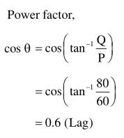
Ques 17. The active and reactive power of an inductive circuit are 60 W and 80 VAR respectively. The power factor of the circuit is
0.8 lag
0.5 lag
0.6 lag✔
0.75 lag
Active Power P = 60 W
Reactive Power Q = 80 VAR
S =√P2 + Q2 = √602 + 802
= 100 VA
Power factor = cos Φ = P/S = 60/100 =0.6
Second Method
Ques 18. For which of the following the excitation control method is satisfactory?
Long Lines
Low Voltage lines
High Voltage Lines
Short Lines✔
When the load on the supply system changes, the terminal voltage of the alternator also varies due to the changed voltage drop in the synchronous reactance of the armature.
The voltage of the alternator can be kept constant by changing the field current of the alternator in accordance with the load. This is known as an excitation control method. The excitation of the alternator can be controlled by the use of an automatic or hand-operated regulator acting in the field circuit of the alternator.
The excitation control method is satisfactory only for relatively short lines. However, it is not suitable for long lines as the voltage at the alternator terminals will have to be varied too much in order that the voltage at the far end of the line may be constant.
Ques 19. The type of protection that does not respond to a fault occurring beyond its zone even though the fault current may pass through the zone is
Back up protection
Busbar protection
Unit Protection✔
Generator Protection
Unit Protection Scheme:
Unit type protection is also called main protection or primary protection it protects a specific area of the system such as a transmission line, transformer, generator, or bus bar. The unit protection scheme is based on Kirchhoff’s Current Law – the sum of the currents entering an area of the system must be zero Any deviation from this must indicate an abnormal current path.
This protection scheme is based on the principle of selectivity i.e the effects of a disturbance or operating condition outside the area of interest are totally ignored and the protection must be designed to be stable above the maximum possible fault current that could flow through the protected area.
Ques 20. If F is the load factor the loss load factor is given by
0.35 F + 0.7 F2
0.25 F + 0.75 F2✔
0.25 F2 + 0.85 F
0.75 F + 0.20 F2
Loss load factor
Several empirical formulae are available to determine the Loss load factor
Loss load factor is the ratio of average power losses to the power losses at peak demand
Loss load factor = Average power losses/Power losses at peak demand
Loss load factor can also be determined by
Loss load factor = 0.25 x (load factor) + 0.75 x (load factor)2