The 2’s complement of the number (1010101)2 is found in two steps. First, convert the given number into its l’s complement.
1’s complement of a binary number is just an inversion of individual bits.
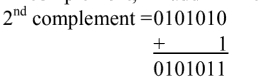
1’s complement of (1010101)2 is (0101010)2
To find 2’s complement of the number add one to the least significant bit (LSB). So
Ques.92. Under no-load conditions in transmission lines, the receiving end voltage is greater than the sending end voltage. This effect is called
Corona effect
Ferranti effect
Proximity effect
Skin effect
Answer.2. Ferranti effect
Explanation:-
Ferranti Effect
In transmission lines, the voltage at the receiving end is less than the voltage at the sending end. This is because the line has voltage drops due to resistance and inductive reactance. In the case of long transmission lines, when the line is lightly loaded or open-circuited, it is found that the receiving-end voltage is more than the sending-end voltage. This happens because of the charging current in the line. Moreover, when the line is lightly loaded, the line voltage drop is also small. This phenomenon is known as the Ferranti effect.
During the light loading or open condition of the line, when the receiving-end voltage is more than the sending-end voltage, it is known as the Ferranti effect.
In the high-voltage or extra-high-voltage line, the shunt reactors are used which absorb some part of the charging current and restrict the voltage to safe limits.
Ques.93. ______Earthing is the best form of earthing and is very cheap in cost?
Pipe
Plate
Strip
Rod
Answer.1. Pipe
Explanation:-
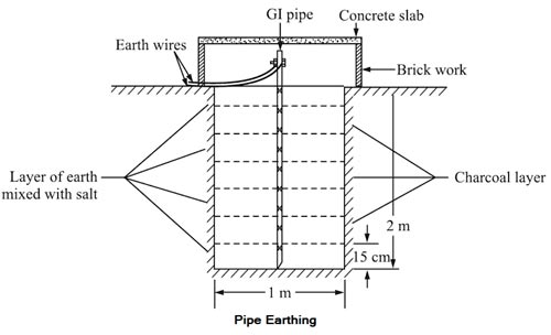
Taking into consideration, the factors such as initial cost, inspection, resistance measurement, etc., G.I. pipe earthing is the best form of ground connection. Iron is the cheapest material and remains serviceable even if put in the salty mass of earth. Pipe earthing is the common method of earthing done using G.l. of diameter 3.8 cm. A pit of about 40 cm square area and 2 to 5-meter depth is dug in the soil. To increase the dampness and moisture, charcoal and salt are filled in the pit in alternate layers up to about two meters from the bottom. An earth pipe can be protected from mechanical damage by covering it with cement concrete work. A funnel with mesh can also be provided to pour water.
In this method of earthing a G.I. pipe of 38 mm diameter and 2-meter length is embedded vertically into the ground. This pipe acts as an earth electrode. The depth depends on the condition of the soil.
The pit area around the pipe is filled with salt and coal mixture for improving the condition of the soil and earthing efficiency. According to the Indian standard, the pipe should be placed at a depth of 4.75 m.
Ques.94. The names of the four materials have been given, select the one which has the least resistivity at 20°C?
Iron
Silver
Glass
Nichrome
Answer.2. Silver
Explanation:-
The resistivity of iron at 20°C is 9.71 × 10⁸
The resistivity of silver at 20°C is 1.59 × 10⁸
The resistivity of Glass at 20°C is 1.10 × 10⁹
The resistivity of nichrome at 20°C is 100 × 108
Hence silver is the least resistive material in the given option.
Ques.95. A diode appears as in forward region of its characteristics?
A capacitor
A high resistor
An OFF switch
An ON switch
Answer.4. An ON switch
Explanation:-
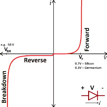
A P-N junction acts as a voltage-controlled switch. During forward biasied the p-n junction diode acts like an ON switch. When reverse biased, it acts like an OFF switch.
Ques.96. The force experienced by a current-carrying conductor lying parallel to a magnetic field is
Zero
BIL
BIL cosφ
BIL sinφ
Answer.4. BIL sinφ
Explanation:-
FORCE ON CURRENT CARRYING CONDUCTOR PLACED IN UNIFORM MAGNETIC FIELD
We know that a moving charge in a magnetic field experiences a force. Now electric current in a conductor is due to the drifting of free electrons in a definite direction in the conductor. When such a current-carrying conductor is placed in the uniform magnetic field, each free electron experience! a force. Since the free electrons are constrained ii the conductor, the conductor itself experiences a force. Hence, a current-carrying conductor placed in a magnetic field experiences a force.
Expression for the force.
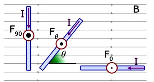
Consider a conductor of length I and area of cross-section A placed at an angle θ to the direction of a uniform magnetic field Β as shown in the figure
F = B.I.L.sinθ
Special case:-
When θ = 0° or 180° i.e sinθ = 0
F = 0 (Minimum value)
Thus if a current-carrying conductor is placed parallel to the direction of the magnetic field, the conductor will experience no force.
When θ = 90° sinθ = 1
F = 1 (maximum value)
Hence, a current-carrying conductor will experience a maximum force when it is placed at right angles to the direction of the magnetic field.
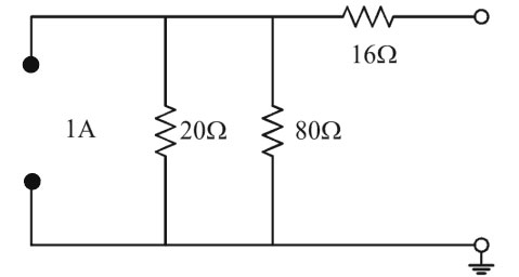
Ques.97. Observe the given figure. Find Thevenin’s resistance as seen from open-circuited terminals?
4 Ω
32 Ω
16 Ω
8 Ω
Answer.2. 32 Ω
Explanation:-
To find the Thevenin’s resistance the current source is open-circuited and the voltage source is short-circuited.
The resistance 20Ω and 80Ω are in parallel and they both are connected in series with 16Ω resistors.
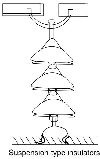
Ques.98. In a suspension type insulator the voltage…..?
Across the top disc is minimum
Across the center disc is minimum
Across the top disc is maximum
Across the center disc is maximum
Answer.3. Across the top disc is maximum
Explanation:-
Suspension-type insulator consists of a number of porcelain discs connected in series by metal links in the form of a string. The conductor is suspended at the bottom end of this string while the other end of the string is secured to the cross arm of the tower.
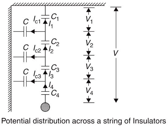
When ac voltage is applied across the insulator string, the voltage across each unit is not the same. This is because there is a capacitance between the units as well as the capacitance between each unit and earth or frame-work. The insulator units have capacitance between the about 6 to 10 times the capacitance of the unit to earth.
Due to the shunt capacitance, the charging current is not the same through all the discs of the string. Therefore, the voltage across each disc will be different. Presence of self-capacitance and shunt capacitance results in the
Non-uniform potential distribution of voltage across the individual discs of suspension-type insulators.
The disc nearest to the conductor has a maximum voltage across it.
The disc nearest to the conductor is under maximum electrical stress and is likely to be punctured.
Since the insulator capacitances are ineffective for DC, the voltage across each disc would be the same for DC voltage across the string.
Ques.99. In the two-wattmeter method of three-phase power measurement of a balanced load, if the reading of one meter is −200W, then the power factor of the load is
Equal to 0.5
Greater than 0.5
Less than 0.5
Equal to zero
Answer.3. Less than 0.5
Explanation:-
The reading of two wattmeters can be expressed as
W1 = VLILcos(30 + φ)
W2 = VLILcos(30 − φ)
(i) When PF is unity ( φ = 0°)
W1 = VLILcos30°
W2 = VLILcos30°
Both wattmeters read equal and positive reading i.e upscale reading
(ii) When PF is 0.5 (φ = 60°)
W1 = VLILcos90° = 0
W2 = VLILcos30°
Hence total power is measured by wattmeter W2 alone
(iii) When PF is less than 0.5 but greater than 0 i.e ( 90° > φ > 60°)
The wattmeter W2 reads positive (i.e.upscale) because for the given conditions (i.e. ( 90° > φ > 60°), the phase angle between voltage and current will be less than 90°. However, in wattmeter W1, the phase angle between voltage and current shall be more than 90° and hence the wattmeter gives negative (i.e. downscale) reading.
Ques.100. An ideal transformer will not transform?
I. Power
II. Current
III. Frequency
IV. Voltage
II and III
Ill and IV
I and III
I and II
Answer.3. I and III
Explanation:-
All transformer configurations obey the law of conservation of energy. In transformers, this can be interpreted as the equality of the products of voltage and current or power in both primary and secondary windings, except for losses. Thus, the power input at the primary winding is nearly equal to the power output at the secondary winding.
If, for example, the voltage at the secondary terminals of the transformer is twice that of the primary terminals, the current at the secondary terminals must be about half that at the primary terminals to keep the product of voltage and current, which is equal to power, constant.
An ideal transformer would be 100 percent efficient because the power output would be equal to the power input. But, because losses reduce the efficiency of most transformers to about 90 percent, the output power is about 10 percent less than the input power. The total loss is the sum of ohmic resistance loss, eddy-current induction loss, and hysteresis (molecular friction) loss, all caused by the changing polarity of the applied current.
For SSC JE 2019 SET-1 Electrical paper with complete solutionClick Here
For SSC JE 2018 SET-1 Electrical paper with complete solutionClick Here
For SSC JE 2018 SET-2 Electrical paper with complete solutionClick Here
For SSC JE 2018 SET-3 Electrical paper with complete solutionClick Here
For SSC JE 2018 SET-4 Electrical paper with complete solutionClick Here
For SSC JE 2018 SET-5 Electrical paper with complete solutionClick Here