Ques.61. Which of the following generators offers the poorest voltage regulation?
Differential compounded
Shunt
Cumulative compounded
Series Motor
Answer.1. Differential compounded
Explanation:-
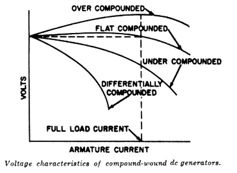
Voltage regulation refers to automatic changes in the terminal voltage due to reactions within the generator as the load current changes.
There are two types of compound DC motors:
Cumulative compound
Differential compound
In the cumulative compound DC motor, series and shunt field fluxes are both in the same direction and therefore add up (i.e., cumulative compound.) Under a full-load condition, the series windings help to produce a stronger field and therefore more torque. However, under a no-load condition, the shunt winding helps in creating a weaker field; hence, the “danger of runaway speed” exists. The speed regulation of a cumulative compound motor is worse than that of a shunt motor, but it will generate larger torque.
In differential compound motors, series and shunt fields are in opposite directions, and they, therefore, subtract from each other (i.e., differential compound). For larger loads, the series field strength is stronger than that of the shunt field, and for smaller loads, the series field strength is weaker than that of the shunt field. In both cases, the fields subtract from each other; therefore, a constant motor speed condition is possible. This motor has good speed regulation but small starting torque.
In the differential compound motor, an increase in load creates an increase in current and a decrease in total flux in this type of motor. These two tend to offset each other and the result is a practically constant speed. However, since an increase in load tends to decrease the field strength, the speed characteristic becomes unstable.
The differential compound generator is used as a constant-current generator for the same constant-current applications as the series generator. It has no practical use as a dc voltage generator as the voltage regulation is very poor.
Ques.62. A _____ transformer is usually mounted on a pole of plinth?
Distribution
Power
Potential
Current
Answer.1. Distribution
Explanation:-
Distribution substation may be subdivided into the following types:
H-polo mounted: Transformers of low rating say 25, 40, 63, 100, and 200 kVA are mounted on rolled steel fixtures which are rigidly fastened to the two poles.
Platform mounted: A platform is constructed on a four-pole structure for placing the transformer on it. Platform mounting is done for transformers of capacity 250, 300, and OCO kVA.
Plinth or foundation mounted: Transformers above 500 kVA are placed on a plinth or foundation with a wall or fence surrounding it. Plinth or foundation mounted substations can be installed outdoor or indoor. The equipment installed should be enclosed by a fence or a wall. The switchgear consists of circuit breakers. isolators etc. In Indoor substations, the transformer. switchgear and the allied equipment are installed inside a building.
Ques.63. While estimating the overhead lines, if the number of poles required is 14, then what is the estimated number of earth sets required?
2
3
5
4
Answer.4. 4
Explanation:-
While estimating the overhead lines, the first and last pole is always earth connected and after every 3rd electrical pole, the fourth pole is earthed. Therefore, the approximate number of required ground set = 4
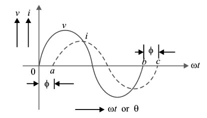
Ques.64. If the AC voltage and current are given by the following expressions?
v = 200sin (314t — 60°)
i = 50sin (720t), then what is the phase relation between them?
Can’t be determined
Voltage and current are in phase
Voltage leads current by 60°
Voltage lags current by 60°
Answer.1. Can’t be determined
Explanation:-
When two alternating quantities of the same frequency have different zero points, they are said to have a phase difference. The angle between zero points is the angle of phase difference φ.
In the above-given question, the frequency of voltage and current is different so we can’t calculate the phase difference between them
Ques.65. A/An is used in domestic mixers?
Shaded pole motor
Permanent magnet synchronous motor
Induction motor
Universal motor
Answer.4. Universal Motor
Explanation:-
We use universal motors in mixer grinders. Universal motors can run both on a.c. and d.c.
The universal motor works on the same principle that DC series motor works. DC series motor has the characteristics of operating at high-speed when there is no load and operating at low-speed when the load is applied. It has high starting torque characteristics.
So it is used in mixers, where initially we put some load at starting.
Ques.66. If two impedances are given as Z1 = 20∠60° and Z2 = 5∠30°, then Z1/Z2 = ?
This law relates to work done in a magnetic circuit i.e. closed magnetic flux path.
The work done on or by a unit N-pole in moving once round any complete path is equal to the product of current and number of turns enclosed by that path
$\oint {{H_r}{d_r} = } NI$
where
H= magnetizing force at a distance r.
Ques.68. The impedance at resonance offered by a parallel resonant circuit is
Maximum given by L/CR
Minimum given by I/CR
Maximum given by I/CR
Minimum given by L/CR
Answer.1. Maximum given by L/CR
Explanation:-
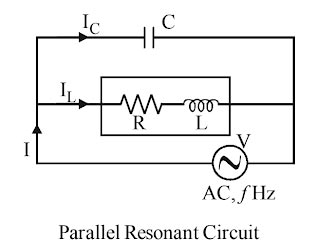
A parallel resonant circuit (also called a resonant or tank circuit) has a coil and a capacitor in parallel. It is said to resonate when the reactive (or wattless) component of line current I reduce to zero.
A practical parallel resonance circuit is represented by an inductance and a resistance id one branch and a capacitance in other branches.
At resonance in a practical parallel resonance circuit, the impedance is maximum. Hence, it is called a rejector circuit, and it exhibits the property of voltage magnification.
Z = L/CR
The line current in the parallel resonance circuit is minimum.
I = V/L/CR
Ques.69. Observe the given table. The truth table represents gate?
INPUTS
OUTPUTS
X
Y
Z
0
0
0
0
1
1
1
0
1
1
1
0
OR
AND
NAND
XOR
Answer.4. XOR
Explanation:-
In the exclusive OR gate (XOR gate) has two inputs
The ouput will be 1 when either input is 1 i.e X = 1 and Y = 1, but not when both the inputs are 1.
If both the input is zero i.e X = 0 and Y = 0, then the output is 0.
INPUTS
OUTPUTS
X
Y
Z
0
0
0
0
1
1
1
0
1
1
1
0
Ques.70. The number of valence electrons of P and Si are respectively?
5 and 4
4 and 4
3 and 4
4 and 5
Answer.1. 5 and 4
Explanation:-
Phosphorus (P) has 15 electron i.e 2,8,5. Hence the number of electron in its outermost orbit is 5.
Silicon (Si) has 14 electron i.e 2,8,4. Hence the number of electrons in its outermost orbit is 4.