Ques 31. A moving coil instrument has a resistance of 10Ω and gives full-scale deflection at 0.5 V potential difference across it. How can it be adapted to measure a current up to 100 A? (SSC-2014 Set-2)
By connecting shunt resistance of 0.005 Ω across the meter
By connecting shunt resistance of 0.05 Ω across the meter
By connecting shunt resistance of 5 Ω across the meter
By connecting shunt resistance of 10Ω across the meter
Answer.1. By connecting shunt resistance of 0.005 Ω across the meter
Explanation:-
Let shunt resistor R is connected in parallel
V = IR
Req = R x10/R + 10
0.5 = 100(R x 10)/ R + 10)
0.5R + 5 = 1000R
= 0.005Ω
Ques 32. The multiplying power of the shunt of a milliammeter is 8. If the circuit is 200 mA, then current through the meter is (SSC-2014 Set-2)
25 mA
200 mA
1600 mA
3200 mA
Answer.1. 25 mA
Explanation:-
Multiplying power of the shunt is given as
Multiplying power = I/Im
Where I = current of the circuit to be measured
Im = Current passing through the ammeter
8 = 200/Im
Im = 200/8 = 25mA
Ques 33. The technique of adding a precise amount time between the trigger point and beginning of the scope sweep in a CRO is known as (SSC-2014 Set-2)
Free running sweep
Delayed sweep
Triggered sweep
Non-sawtooth sweep
Answer.3. Triggered sweep
Explanation:-
The technique of adding a precise amount of time between the trigger point and the beginning of the scope sweep in a CRO is known as the Delayed sweep. A useful sweep range is from one second to 100 nanoseconds, with appropriate triggering and (for analog instruments) sweep delay. A well-designed, stable trigger circuit is required for a steady display. The chief benefit of a quality oscilloscope is the quality of the trigger circuit.
Ques 34. In a CRO, a sinusoidal waveform of a certain frequency is displayed. The value of the quantity that can be made out by observation is (SSC-2014 Set-2)
RMS value of the sine wave
The average value of the sine wave
The form factor of the sine wave
Peak- peak value of the sine wave
Answer.4. Peak- peak value of the sine wave
Explanation:-
CRO is voltage-dependent instruments and can be used for the measurement of the voltages at any frequency within the range of the CRO. CRO measure Peak to the Peak value of sine wave because from the peak value of AC signal the RMS and other parameters can be determined such as distortion
Ques 35. In a Cathode Ray Tube, the focusing anode is located (SSC-2014 Set-2)
After accelerating anode
Between pre-accelerating and accelerating anode
Before pre-accelerating anode
Just after electron-guns
Answer.2. Between pre-accelerating and accelerating anode
Explanation:-
The electron gun assembly consists of six parts i.e an indirectly heated cathode, a control, grid surrounding the cathode, a focusing anode and an accelerating anode and a pre accelerating anode. And the focusing anode is located between pre-accelerating and accelerating anode.
The pre accelerating anode and accelerating anode are at a higher potential than the focusing anode, therefore, these anodes create an electric field between them and act as a lens with a focus on the screen.
Ques 36. In indicating instrument the springs are mainly used to (SSC-2013)
Conduct the current on the coil
Hold the pivot in position
Control the pointer movement
Reduce the vibration of the pointer
Answer.3. Control the pointer movement
Explanation:
Spring provides the controlling force in the measuring instrument if the controlling force is absent the pointer will not comes back to starting position i.e zero when the current is removed.
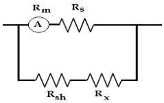
Ques 37. An ammeter of resistance Rm is placed in an arrangement as shown in the figure. The material of Rm , Rsh is copper whereas that of Rs, Rx is manganin. The condition for which the meter performance is compensated against the temperature is (SSC-2013)
1/Rm + 1/Rsh = 1/Rs + 1/Rx
RmRsh = RsRx
Rm + Rsh = RsRx
Rm/Rs =Rsh/Rx
Answer 4. Rm/Rs =Rsh/Rx
Explanation:
The condition for which the meter performance is compensated against the temperature will be when the resistance material is equally balanced
RmRx= RshRx
Rm/Rs =Rsh/Rx
Ques 38. If a 110 V, 50 Hz is supplied across a PMMC voltmeter of full-scale range 0-220 V and internal resistance of 10 kΩ, reading of the voltmeter will be (SSC-2013)
0 V
110 √2 V
78 V
55 V
Answer 1. 0V
For sinusoidal voltage, PMMC reads zero.
PMMC type instrument uses two permanent magnets in order to create the stationary magnetic field. If we apply AC current to these types of instruments the direction of current will be reversed during the negative half cycle and hence the direction of torque will also be reversed which gives the average value of torque zero.
Also If a.c. supply given to these instruments, an alternating torque will be developed. Due to moment of inertia of the moving system, the pointer will not follow the rapidly changing, alternating torque and will fail to show an,y readings
Ques 39. To maximize the driving torque in an induction type instrument, the flux produced by shunt coil and series coil should be (SSC-2013)
In phase with each other
In quadrature with each other
Displaced by 45° with respect to each other
Out of phase with respect to each other
Answer.2. In quadrature with each other
Explanation:
The Deflecting torque of Induction type Instrument is given as:
Td = Φ1Φ2 sinβ cosα
where Φ = flux
β & α are the phasor angle
The torque in the Induction type instrument is directly proportional to the cosα. Therefore in order to maximize the torque, the angle “α” should be near to zero.
The torque in the Induction type instrument is directly proportional to the sinβ. Therefore the angle β should be nearer to 90° in order to maximize the torque. The angle β is the angle between two shunt coil flux and the series coil flux and quadrature means 90°.
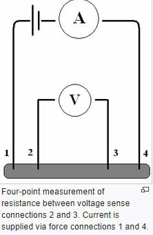
Ques 40. To minimize the error due to lead and contact resistances, low resistances used in electrical measurement work are provided with (SSC-2013)
Guard Rings
Four Terminals
Thick Insulation
Metal shields
Answer.2. Four Terminals
Explanation:
Four-terminal sensing
Four-terminal sensing is also known as Kelvin sensing, which measures very low resistances using four-terminal sensing. Each two-wire connection can be called a Kelvin connection.
When a Kelvin connection is used, the current is supplied via a pair of source connections (current leads). These generate a voltage drop across the impedance to be measured according to Ohm’s law V=IR.
A pair of sense connections (voltage leads) are made immediately adjacent to the target impedance so that they do not include the voltage drop in the force leads or contacts.
Since almost no current flows to the measuring instrument, the voltage drop in the sense leads is negligible hence accurate measurement can be obtained.
It is usual to arrange the sense wires as the inside pair, while the force wires are the outside pair.