Ques 71. The compensating winding in the DC machine is
Located in the armature slot for the compensation of armature reaction
Located on commutating poles for Improving the commutation
Located on pole shoes for avoiding the flashover at the commutator surface.
Located on the pole shoe to avoid the sparking at the brushes
Answer 3. Located on pole shoes for avoiding the flashover at the commutator surface.
Explanation:-
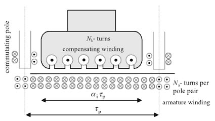
The purpose of compensating windings in DC machines is to compensate for harmful flux components created by armature windings. Flux components are harmful because they create an unfavorable air-gap flux distribution in DC machines. The dimensioning of compensating windings is based on the current linkage that has to be compensated by the compensating, winding. The conductors of a compensating winding have therefore to be placed close to the surface of the armature, and the current flowing in them has to be opposite to the armature current. In DC machines, the compensating winding is inserted in the slots of the pole shoes The compensating effect has to be created in the section of the pole pitch, as illustrated in Figure.
Another Explanation of the same question can be
Compensating windings are used to overcome the commutation and cross-magnetization of armature reaction, which causes high flux density in trailing pole tip. Also, the coil under this tip can develop the induced voltage that is high enough to cause a flashover between nearby commutator segments. Physically, this coil is much closer to the commutation zone in which the air temperature can be high due to the commutation process. Therefore, the compensating windings are located on pole shoes to avoid flashover.
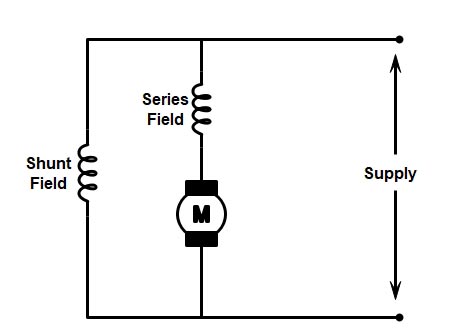
Ques 72. A cumulative compound long shunt motor is driving a load at rated torque and rated speed. If the series is shunted by a resistance equal to the resistance of the series field, keeping the torque constant.
The armature current increase
The motor speed increases
The armature current decreases
The motor speed decreases
Answer.1.The armature current increases
Explanation:-
As discussed in (question number 58.)The torque developed by a d.c motor is directly proportional to Flux per pole × Armature Resistance i.e
T ∝ ΦIa
The diagram of the above question is given below
In a cumulative compound long shunt motor, a load is being driven at rated torque and rated speed and its series field is shunted by a resistance equal to series field resistance with constant torque. Due to new resistance, the current is halved of its original value. Therefore, the armature current will have to increase to keep torque constant. Hence, the armature current increases to keep torque constant.
Ques 73. Neglecting all losses, the developed torque (T) of a DC separately excited motor, operating under constant terminal voltage, is related to its output power (P) as under:
T ∝ √P
T ∝ P
T is independent of P
T2 ∝ P3
Answer 2.T ∝ P
Explanation:-
Relation of output power and torque under constant terminal voltage can be given as
The torque developed by a d.c motor is directly proportional to Flux per pole × Armature Resistance i.e
T ∝ ΦIa
T ∝ Ia———1
Output power for the separately excited motor is given as
P = EbIa.
If voltage supply is constant then power is
P∝ Ia……………. (2)
From equation (1) and (2),
T ∝ P.
or
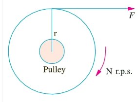
Consider a pulley of radius r meter acted upon by a circumferential force of F Newton which causes it to rotate at N r.p.m.
The angular speed of the pulley is
ω = 2πN/60 rad/sec
Work done by this force in one revolution
= Force × distance = F × 2πR Joule
The power developed = Work Done/Time
= (F × 2πR)/60/N
= (F × R) × (2πN)/60
The power developed = T × ω watt or P = T ω Watt
From the relation of power developed in the armature is equivalent to mechanical torque developed, is
P = T × ω
Where P = Output power of separately excited motor and it is given as P = EbIa ω = Angular speed in rad/sec. and it is given as ω = 2πN ⁄ 60
where N = Speed of motor in rpm, Eb = induced back emf, Ia = armature current.
If voltage supply is constant then power is
∴ T∝ power output P will be equal to power developed in the armature. ∴ T ∝ P.
Ques 74. A separately excited DC motor has an armature resistance of 0.5 W. It runs from a 200 V DC supply drawing an armature current of 20 A at 1500 rpm. For the same field current, the torque developed for an armature current of 10 A will be
23.59 N-m
34.76 N-m
15.28 N-m
19.99 N-m
Answer. 3.15.28 N-m
Explanation:-
Given parameters Ra = 0.5 ohm
Supply Voltage V = 250 V Armature current Ia = 20 A Speed N = 1500 rpm Armature current Ia = 20 A Torque T =?
From the voltage equation, the back EMF of DC motor is
Eb = V − IaRa
= 250 − 20 × 0.5
Eb = 240
The torque of DC motor is
T = P ⁄ ω
Where P = Output power of separately excited motor and it is given as P = EbIa ω = Angular speed in rad/sec. and it is given as ω = 2πN ⁄ 60
Hence for the armature current of 10 A the torque developed is
T =EbIa× 60 ⁄ 2πN
= 240 × 10 × 60 ⁄ 2π × 1500
= 15.28 N-m
Ques 75. A separately excited 300 V DC shunt motor under no-load runs at 900 rpm drawing an armature current of 2 A. The armature resistance is 0.5 Ω and the leakage inductance is 0.01 H. When loaded, the armature current is 15 A. Then the speed in rpm is.
881 RPM
780 RPM
1000 RPM
1200 RPM
Answer.A.881 RPM
Explanation:-
Given Data
Supply Voltage V = 300 V No-Load Speed No = 900 RPM Armature current at no-load Ia = 2 A Armature Resistance Ra = 0.5 Ω Leakage Inductance = 0.01 H Armature current at full load Io= 15A
⇒ From the voltage equation, the back EMF of DC motor at no-load
Ebo = V − IaRa
= 300 × 2 × 0.5
Ebo = 299 V
⇒ The back EMF of DC motor on Loaded
Eb = V − IaRa
= 300 × 15 × 0.5
Eb = 292.5 V
Let the on load speed be N. As we know that back EMF of DC motor is directly proportional to the flux and speed.
Eb ∝ Nφ Eb ∝ N (φ is constant)
The ratio of emf and speed can be equated at on load and no-load condition.
Ques 76. For an application that requires smooth and precise speed control over the wide range, the motor is preferred is
Squirrel cage Induction Motor
Synchronous Motor
DC motor
Wound Rotor Induction Motor
Answer.3.DC Motor
Explanation:-
A DC motor is any of a class of rotary electrical machines that converts direct current electrical energy into mechanical energy. Controlling the speed of DC motors is a crucial matter since different machines and equipment have different aspects and output speed or torque requirements in which prospect. Speed Control may require to be very precise and over wide ranges as well. So before implementing the proposed system an engineer needs to understand its operation and according to that how the speed of the drive wit] be controlled needs to be decided by him with proper care.
Generally, the rotational speed of a DC motor is proportional to the voltage applied to it, and the torque is proportional to the current. Speed control can be achieved by variable battery tapings, variable supply voltage, resistors, or electronic controls. The direction of a wound field DC motor can be changed by reversing either the field or armature connections but not both. This is commonly done with a special set of contactors (direction contactors). The effective voltage can be varied by inserting a series resistor or by an electronically controlled switching device made of thyristors, transistors or, formerly, mercury arc rectifiers.
Speed control over a wide range both above and below the rated speed: The attractive feature of the dc motor is that it offers a wide range of speed control both above and below the rated speeds. This can be achieved in dc shunt motors by methods such as the armature control method and field control method. This is one of the main applications in which dc motors are widely used in fine speed applications such as in rolling mills and in paper mills. High starting torque: DC series motors are termed as best suited drives for electrical traction applications used for driving heavy loads in starting conditions. DC series motors will have a starting torque as high as 500% compared to normal operating torque. Therefore dc series motors are used in the applications such as electric trains and cranes. Accurate steep less speed with constant torque: Constant torque drives are one such drives that will have motor shaft torque constant over a given speed range. In such drives, shaft power varies with speed.
Quick starting, stopping, reversing, and acceleration
Free from harmonics, reactive power consumption, and many factors which make dc motors more advantageous compared to ac induction motors.
Ques 77. The most commonly used method of speed control of a D.C motor is by varying the
The voltage applied to the motor
Field Strength
Armature circuit Resistance
Effective number of conductors in series
Answer 2.Field Strength
Explanation:-
Field control is the most common method and forms one of the outstanding advantages of shunt motors. The method is, also applicable to compound motors. Adjustment of field current and hence the flux and speed by adjustment of the shunt field circuit resistance or with a solid-state control when the field is separately excited is accomplished simply, inexpensively, and without much change in motor losses.
The speed of DC Motor is inversely proportional to the field current and flux.
N ∝ 1 ⁄ If
or N ∝ 1/φ
By decreasing the flux the speed can be increased and vice versa. Hence this method is also called as a flux control method.
The lowest speed obtainable is that corresponding to the maximum field current
The highest asleep is limited electrically by the effects of armature reaction under weak-field conditions in causing motor instability and poor commutation.
Since the voltage across the motor remains constant, it continues to deliver constant output. This characteristic makes this method suitable for fixed output loads.
Advantages:
The merits of this method are:
Good working efficiency.
Compact controlling equipment
The capability of minute speed control.
The speed is not affected by load, and speed control can be performed effectively even at light load
Relatively inexpensive and simple to accomplish both manually and automatically.
Within limits, field control does not affect ape regulation in the cases of the shunt, compound, and series motors.
Provides relatively smooth and stepless control of the speed.
Disadvantages
The demerits of field control as a method of speed control are:
Inability to obtain speeds below the basic speed.
Instability at high speeds because of armature reaction.
Commutation difficulties and Possible commutator damage at high speeds.
Shunt Motors:
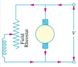
The flux of a D.C. shunt motor can be changed by changing shunt field current (Ish) with the help of a shunt field rheostat as shown in Fig. Since the field current is very small, the power wasted in the controlling resistance is very small.
In the non-interpolar machine, the speed can be increased by this method in the ratio 2:1.
In machines fitted with interpoles the ratio of maximum to minimum speeds of 6: 1 is fairly common.
Series Motor
In a series motor, the variation of flux can be brought about in any one of the following ways
Field Diverter
Armature Diverter
Tapped field control
Paralleling Field control
Ques 78. A 240 V DC series motor takes 40 A when giving its rated output at 1500 rpm. Its resistance is 0.3 Ω. The value of resistance that must be added to obtain rated torque at 1000 rpm is
6Ω
5.7Ω
2.2Ω
1.9Ω
Answer. D.1.9Ω
Explanation:-
Supply Voltage V = 300 V Rated Speed N1 = 1500 RPM Armature current at no-load Ia = 40 A Armature Resistance Ra = 0.3 Ω N2 = 1000RPM
As it is known the torque is constant, thus armature current and flux will also remain constant. The voltage equation can be given as
Ques 79. The deciding factor in the selection of a d.c. motor for a particular application is its _______ characteristic.
Speed-Torque
Speed -Armature current
Torque -Armature current
None of the above
Answer.1Speed-torque
Explanation:-
Whenever the application of any machine is considered, its operating characteristics along with its economic and technical viability as compared to its competitors are the essential criteria. For a dc machine, of course, the main attraction lies in its flexibility, versatility, and ease of control. This explains why in spite of its rather heavy initial investment it still retains its charm in strong competitive industrial applications. In the world today, around 25% of the motors manufactured are dc motors.
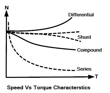
Speed Torque Characteristic
One of the important properties of DC motor is its speed-torque characteristic. Ideally, when the voltage is connected to the motor, it must provide constant torque to accelerate the rotor and when the required speed is reached the torque must become zero. These are also called mechanical characteristics. The nature of these characteristics can easily be obtained by using speed and torque equations.
These characteristics also show how much torque can be developed at a given speed to stay within the rating of the drive. Hence speed-torque characteristics play a very important role in selecting a type of motor for a particular application.
Note:- The availability and economics of dc power is the deciding factor along with the motor characteristics.
In dc series motor the starting torque is very high, up to five times the full-load torque. It may be interesting to note that the maximum torque in a dc motor is limited by commutation and not, as with other motors, by heating. Speed regulation of a dc series motor can be varied widely. For drives requiring a very high starting torque, such as hoists, cranes, bridges, battery-powered vehicles and traction-type loads, the series dc motor is the obvious choice. Speed control is by armature resistance control.
Compound motor characteristics depend naturally upon the degree of compounding. Shunt field of course restricts the no-load speed to a safe value. Its main competitor is the squirrel-cage high-slip induction motet A compound motor has a considerably higher starting torque compared to a shunt motor and possesses a drooping speed-load characteristic. Compound dc motors are used for pulsating loads needing flywheel action, plunger pumps, shears, conveyors, crushers, bending rolls, punch presses, hoists, rolling mill, planning.etc.
A dc shunt motor has a medium starting torque. Speed regulation is about 5-15%. It is used essentially for constant speed applications requiring medium starting torques, such as centrifugal pumps, fans, blowers, conveyors, machine tools, printing presses, etc. Owing to the relative simplicity, cheapness, and ruggedness of the squirrel cage induction motor, the shunt motor is less preferred for constant-speed drives except at low speeds. At low speeds, dc shunt motors are comparable with synchronous motors. The outstanding feature of a dc shunt motor, however, is its superb wide range flexible speed control above and below the base speed using solid-state controlled rectifiers.
In general, whenever a decision is to be made for a choice of a suitable motor for a given application, it is necessary to make the specific, analytic, economic, and technical comparison of all practical choices. Finally, it should be mentioned to the credit of a dc machine that it still remains the most versatile, flexible, easily controllable energy conversion device whose demand and need would continue to be felt in industries in future for various applications discussed above.
Ques 80. The direction of rotation of a DC shunt motor can be reversed by interchanging
The armature terminal only
Either field or armature terminals
The supply terminals
The field terminals only
Answer.2Either field or Armature Terminal
Explanation:
The direction of rotation of a DC shunt motor can be reversed by interchanging the leads of either the field winding or the Armature Winding.
Generally changing the direction of the field is easier, because it carries a lesser current as compared to armature current. However, the reversal should not be done while the armature is excited.