
Ques.31. The transient response of a system is mainly due to ______
- Inertia Forces
- Internal Forces
- Stored Energy
- Friction
Answer.3. Stored Energy Explanation:- In electrical or electronic systems, the term transient designates a period of time during which the system under study is not at its equilibrium state. For instance, it can be the time necessary to let the system startup and reach its nominal output. We knew that circuit elements like capacitors and inductors are energy storing devices. Energy storing elements like a capacitor or an inductor cannot change instantaneously. The time taken by a circuit to change from one steady-state to another steady state is called transient time. Severe transient behavior of a circuit or system having an energy storing element may cause excessive oscillations as the circuit changes from one energy state to the other.
Ques.32. Minority carrier in P-type semiconductor are ________
- Free Electrons
- Free Holes
- Holes and Electrons Both
- Holes minus electrons
Answer.1. Free Electrons Explanation:- The process of adding either a pentavalent element or a trivalent element to a pure semiconductor is called doping. The doped semiconductor is called an extrinsic semiconductor. The doping material that is added to a pure semiconductor is also referred to as impurity material. Depending upon whether a pentavalent or trivalent doping material is added, extrinsic semiconductors are respectively called n-type semiconductors or p-type semiconductors. The number of charge carriers, either an excess of electrons or deficiency of electrons (causing holes in a material), can be altered by doping or adding very small quantities of impurities to a semiconductor material. A doped semiconductor always has an excess of one type of charge carrier. For example, excess electrons make it an N-type semiconductor “N” stands for negative. Excess holes make it a P-type semiconductor.”P” stands for positive. Each of these materials responds to positive or negative current flow oppositely.
Ques.33. A moving iron type ammeter has a few turns of thick wire so that
- Resistance is less
- Sensitivity is high
- Damping is effective
- Scale is large
Answer.1. Resistance is less Explanation:- Moving iron instruments are of two types: attraction type and repulsion type. In both types, the principle of operation is the force experienced by an iron piece in the presence of a magnetic field. The necessary magnetic field is produced by the ampere-turns of a current-carrying coil. When used as an ammeter the coil has fewer turns of thick wire so that the ammeter has low resistance. When used as a voltmeter, the coil has a high impedance so as to draw a small current as possible since it is connected in parallel. Since the current through it would be small, it has to have a large number of turns to produce the necessary ampere-turns.
Ques.34. While checking with a multimeter an open resistor reads _____
- Zero
- Infinite
- High but without tolerance
- Low but not Zero
Answer.2. Infinite Explanation:- Since in an open circuit the value of current is zero this is only possible when the resistance of the circuit is infinite because the higher the resistance less current will flow through the circuit.
Ques.35. In amplitude modulation
- The amplitude of the carrier kept constant
- Change occurs in the carrier frequency
- Amplitude is varied according to the instantaneous value of modulating wave
- None of these
Answer.3. Amplitude is varied according to the instantaneous value of modulating wave Explanation:- Modulation is the process of modifying the characteristics of one signal in accordance with some characteristic of another signal. In most cases, the information signal, be it voice, video, binary data, or some other information, is normally used to modify a higher-frequency signal known as the carrier. The information signal is usually called the modulating signal, and the higher-frequency signal which is being modulated is called the carrier or modulated wave. The carrier is usually a sine wave, while the information signal can be of any shape, permitting both analog and digital signals to be transmitted. In most cases, the carrier frequency is considerably higher than the highest information frequency to be transmitted. Amplitude Modulation In AM, the information signal varies the amplitude of the carrier sine wave. In other words, the instantaneous value of the carrier amplitude changes in accordance with the amplitude and frequency variations of the modulating signal. The figure shows a single-frequency sine wave modulating a higher-frequency carrier signal. Note that the carrier frequency remains constant during the modulation process but that its amplitude varies in accordance with the modulating signal. An increase in the modulating signal amplitude causes the amplitude of the carrier to increase. Both the positive and negative peaks of the carrier wave vary with the modulating signal. An increase or decrease in the amplitude of the modulating signal causes a corresponding increase or decrease in both the positive and negative peaks of the carrier amplitude.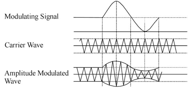
Ques.36. Oscillator operates on sub-harmonic frequency because
- Lower frequency gives better stability
- It gives linear output
- Less stages are used
- More stages are used
Answer.2. It gives a linear output Explanation:-
Ques.37. Hopkinson’s Test on the DC machine is conducted at
- No-load
- Part Load
- Full-load
- Overload
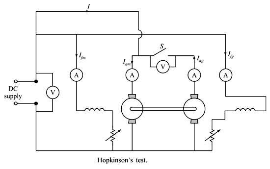
Answer.3. Full load Explanation:- Hopkinson’s test is also referred to as the regenerative or Back-to-Back test. In Hopkinson’s test, we require two identical dc machines. This is a regenerative test. Both the dc machines are mechanically and electrically coupled and are tested simultaneously. Hopkinson’s test is conducted on full load. One of the machines will act as a dc motor and the other as a dc generator. The motor will rotate the generator and the generator will supply power to the motor. Now the question arises, if both machines help each other, then which one will supply the losses. The answer is external dc supply, which means, the input of the external supply will provide the power losses of both the machines. Now the voltage across switch S should be zero and only then we can declare that similar polarities of the machines are connected. So, when the switch S is closed both the dc machines are in perfect parallel connection and there is no chance of the presence of circulating currents between the two machines. Since in the case of the generator, the induced emf minus the armature drop is the terminal voltage and in the case of the motor the induced emf plus the armature drop is the terminal voltage, the excitation of the generator will be more than the excitation of the motor to maintain the terminal voltages equal to one another. Obviously, the no-load iron loss and stray loss will not be equal for both the machines even though the machines are identical in all respects. Stray load loss is a very important factor in determining the efficiency of a dc machine. If we ignore this, we cannot determine the actual efficiency of the dc machine properly due to the following reasons. Stray load loss is the additional copper loss that occurs in the conductors on account of the non-uniform distribution of alternating currents. This increases the effective resistance of conductors and that is nothing but the skin effect. When the conductors carry load current, the teeth of the core get saturated and as a result, more flux passes down the slots through the copper conductors and thus setting up the eddy current losses in them. Due to the flux distortion, the net increase in the core loss occurs and the extra core loss is nothing but the core stray load loss. Advantages of Hopkinson’s Test Drawbacks of Hopkinson’sTest Hopkinson’s Test
Ques.38. Emitter follower is also called as
- Common emitter
- Common base
- Common collector
- SCR
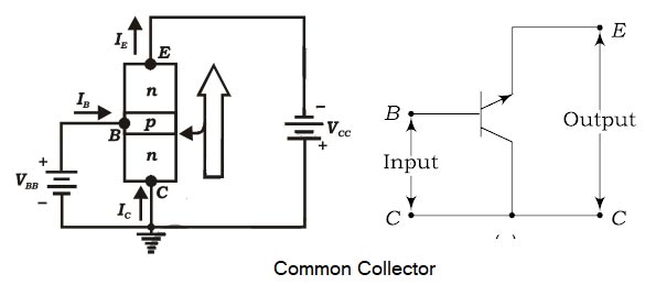
Answer.3. Common collector Explanation:- In a common-collector configuration, the collector terminal of a transistor is connected as a common terminal between input and output as shown in fig. The base and collector terminals are used to apply the input signal whereas the output signal is obtained. The CC configuration is also commonly known as the emitter follower or the voltage follower. This is because the output signal across the emitter is almost the replica of the input signal with little loss. In other words, there is no phase inversion between input and output in the emitter follower circuit. The output voltage is in phase with the input voltage and hence the voltage gain will be a maximum of one. The common-collector configuration is used primarily for impedance-matching purposes since it has a high input impedance and low output impedance, opposite to that of the common-base and common-emitter configuration.Common-Collector Configuration
Ques.39. In connection with an oscillator, which is a FALSE statement?
- Oscillator converts D.C into A.C
- The oscillator is that amplifier that provides its own input
- All types of oscillators produce the sine wave
- In phase, feedback used in the oscillator is also called positive feedback
Answer.3. All type of oscillator produce the sine wave Explanation:- Generally, oscillators are classified into two broad categories according to wave shapes such as Sinusoidal oscillators produce a sine wave output whereas non-sinusoidal oscillators produce square or pulsed output. A multivibrator circuit is a type of non-sinusoidal oscillator.
Ques.40. Frequency multiplier stage of the transmitter operates under ______
- Class C
- Class A
- Class AB
- Class B
Answer.1. Class C Explanation:- The frequency multiplier is used for converting the narrowband signal into a wideband signal and it raises the carrier frequency. The frequency multiplier stage consists of a non-linear device whose output is tuned to the desired harmonic. A frequency multiplier is a class C amplifier whose output frequency is some integer multiple of the input frequency. Most frequency multipliers increase the frequency by a factor of 2, 3, 4, or 5. Because they are class C amplifiers, most frequency multipliers also provide a modest amount of power amplification. Note:- The amplifiers that are, class A, class B, and class AB amplifiers, are linear amplifiers where the amplitude and phase of the output signal are directly related to the amplitude and phase of the input signal. In applications where linearity is not the main issue and efficiency is of primary concern, class C, class D, class E, and class F amplifiers are used.