Ques.21. If the insulation resistance of 2 m long sample of a cable is 10 MΩ, then the 8m sample of the same will have an insulation resistance of (SSC-2013)
40 MΩ
2.5 MΩ
2 MΩ
5.5 MΩ
Answer.2. 2.5 MΩ
Explanation:
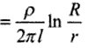
Insulation resistance Riis given as
Where R is the radius of the cable
r is the radius of Core
The insulation resistance varies inversely with the length
As per this question, we use only one conductor so the radius of the conductor, radius of insulation and resistivity of the conductor are constant.
Now the formula become,
R=K/L
we put the value,
R1 x L1 = R2 x L2;
2 x 10 = R2 x 8
R2 = 2.5 MΩ
Ques.22. Two 2000 Ω, 2-watt resistors are connected in parallel. Their combined resistance value and wattage rating are (SSC-2013)
1000 Ω, 2 watt
1000 Ω, 4 watt
2000 Ω, 4 watt
2000 Ω, 2 watt
Answer.2. 1000 Ω, 4 watt
Explanation:
When two resistance R1 and R2 are connected in parallel, the resulting resistance is
(R1 x R2) / (R1 + R2).
(2000 x 2000) / (2000 + 2000)
= 1000 Ω
Wattage of Resistor In Combination
The total wattage of a combination of resistance is always equal to the sum of the individual wattages of the resistor irrespective of whether the combination is series-connected or parallel connected. This is because the total physical size of the combination increases with the addition of the resistance.
Therefore the total wattage for the above question will be 2W + 2W = 4W
Hence the answer will be 1000 ohm and 4 watts.
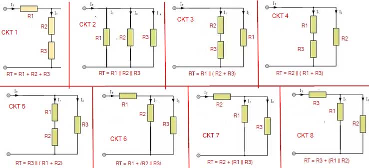
Ques.23. We have three resistances each of value 1 Ω, 2 Ω and 3 Ω. If all the resistances are to be connected in a circuit, how many different values of equivalent resistance are possible? (SSC-2013)
Five
Six
Seven
Eight
Answer.4. Eight
Explanation:
Ques.24. One B.O.T unit is (SSC-2013)
100 kWh
10 kWh
1 kWh
0.1 kWh
Answer.3. 1 kWh
Explanation:
Board of Trade Unit(B.O.T)
Board of Trade Unit(B.O.T) – a unit of energy equal to the work done by a power of 1000 watts operating for one hour
1 kWh = 1 BOT Unit.
Ques.25. An electric heater draws 1000 watts from a 250 V source. The power drawn from 200 V source is (SSC-2013)
800 W
640 W
1000 W
1562.5 W
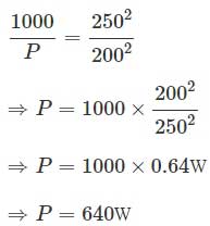
Answer.2. 640 W
Explanation:
The heater draws 1000W of power when connected to a 250V source.
Assume the resistance of the heating element to possess a value R.
Then, the power drawn by the heater Power is given by
P = V2/ R
Assuming the value of resistance to be constant
P ∝ V2
Thus,
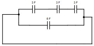
Ques.26. Three 3 μF capacitors are in series. A 6 μF capacitor is in parallel with this series arrangement. The equivalent capacitance of the combination is (SSC-2013)
7 μF
15 μF
3.6 μF
1 μF
Answer.1. 7 μF
Explanation:
The diagram of the above question will be
Now in capacitor connected in parallel, their equivalent capacitance will be
C = 1/C1 + 1/C2 + 1/C3
= 1/3 +1/3 + 1/3
= 1μF
= 1μF
when the capacitors are connected in series their equivalent capacitance will be
C = C1 + C2
= 1 + 6
=7 μF
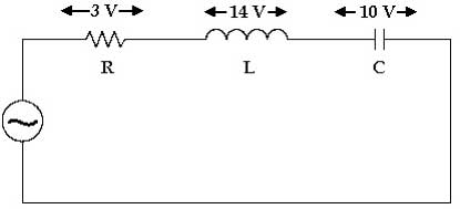
Ques.27. The voltage across R, L and C are 3 V, 14 V and 10 V respectively as in the figure. If the voltage source is sinusoidal, then the input voltage (r.m.s) is (SSC-2013)
10 V
5 V
2.5 V
15 V
Answer.2. 5 V
Explanation:
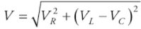
For series RLC circuit the maximum applied voltage is given as
On putting the value
V = 5 v
Ques.28. In the 1-phase series RL circuit fed by a voltage source, the resistance and reactance values are 4 Ω each. In this circuit (SSC-2013)
The current leads the voltage by 45°
The current lags the voltage by 45°
The current lags the voltage by 60°
None of the above
Answer.2. The current lags the voltage by 45°
Explanation:
The phase difference between applied voltage and current is
tanΦ = XL / R = Lω / R
= 4 Ω / 4Ω
or Φ = π/4 = 45°
Hence the current lags the voltage by 45°.
Ques.29. Superposition theorem require as many circuits to be solved as there are (SSC-2013)
Nodes
Sources
Loops
None of the above
Answer.2. Sources
Explanation:
Superposition is used for circuit analysis methods when we have a circuit with multiple inputs or multiple power sources at least two sources are required which can be a voltage source or current source.
To solve the given circuit using superposition theorem the contribution of each individual source, all of the other sources first must be “turned off” (set to zero) by
Replacing all other independent voltage sources with a short circuit (thereby eliminating the difference of potential i.e. V=0; internal impedance of the ideal voltage source is zero (short circuit)).
Replacing all other independent current sources with an open circuit (thereby eliminating current i.e. I=0; internal impedance of the ideal current source is infinite (open circuit)).
Ques.30. A tank circuit consists of (SSC-2013)
An inductor and a capacitor connected in series
An inductor and a capacitor connected in parallel
A pure inductance and a pure capacitance connected in series
A pure inductance and a pure capacitance connected in parallel
Answer.4. A pure inductance and a pure capacitance connected in parallel
Explanation:
An LC circuit, also called a resonant circuit, tank circuit, or tuned circuit is an electric circuit consisting of an inductor, represented by the letter L, and a capacitor, represented by the letter C, connected together in Parallel.