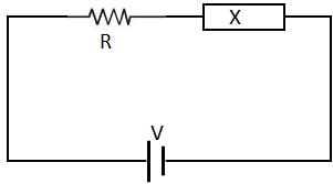
Ques.41. A resistance and another circuit element are connected in series across a dc voltage V. The voltage and zero after time. The other element is pure (SSC-2012)
Capacitance
Both (a) and (c)
Resistance
Inductance
Answer.4. Inductance
Explanation:-
Why inductor behaves as a short circuit for DC voltage?
An inductor has a reactance equivalent XL = 2πfL. Since a DC supply will have frequency = 0, the reactance is 0 and the inductor would be short.
Detail explanation
Imagine a circuit of three elements in the series – an input voltage source, inductor, and resistive load. The input source has been producing some constant (DC) voltage; If an inductor is connected with the DC source, it will not act as inductor but acts like a simple resistor. The current through it will depend on the resistance of the inductor. Now increase the input voltage to a higher value.
The inductor immediately converts the voltage change to an equivalent “anti-voltage” and applies it contrary to the input voltage change, the voltage “produced” by the inductor “jumps” with a magnitude equal to the input voltage change. Thus we have two voltage sources (an “original” and “cloned”:) contrary connected in series and neutralizing each other; as a result, the total (effective) voltage and accordingly the current do not change. After that, the current will increase exponentially (1 – e-t) and reach a constant value. The current will be maximum and the inductor will behave like a short circuit.
Ques.42. For RLC series resonance the current is (SSC-2012)
Minimum at leading P.F
Minimum at Lagging P.F
Maximum at unity P.F
Maximum at leading P.F
Answer.4. Maximum at leading P.F
Explanation:-
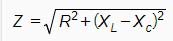
The total impedance of the series LCR circuit is given as
Z = R + j (X1 – X²)
where X1 is inductive reactance
and X2 is capacitive reactance.
At a particular frequency (resonant frequency), we find that X1=X2 because the resonance of a series RLC circuit occurs when the inductive and capacitive reactances are equal in magnitude but cancel each other because they are 180 degrees apart in phase. Therefore, the phase angle between voltage and current is zero and the power factor is unity.
Ques.43. A series RLC circuit resonance at 1 MHZ. At frequency 1.1 MHZ the circuit impedance will be (SSC-2012)
Resistive
Will depend on the relative amplitude of RLC
Capacitive
Inductive
Answer.4. Inductive
Explanation:-
For the Series RLC circuit if the frequency is greater than the resonance frequency than the circuit behaves as an inductive circuit.
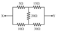
Ques.44. The equivalent resistance between terminal X and Y of the network shown is (SSC-2012)
8Ω
100/3Ω
40/3Ω
20/9Ω
Answer.3. 40/3Ω
Explanation:-
As the given circuit is Wheatstone bridge balance circuit
Therefore according to balanced equation of Wheatstone bridge
Req = 20||40
= (20 x 40)/(20 + 40)
= 40/3Ω
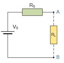
Ques.45. Application of Thevenin’s theorem in a circuit results in (SSC-2012)
An ideal voltage source
An ideal current source
A current source and impedance in parallel
A voltage source and impedance in series
Answer.4. A voltage source and impedance in series
Explanation:-
The Thevenin equivalent resistance Rs is viewed from the open terminals A and B is given as. As per Thevenin theorem, when resistance RL is connected across terminals A and B, the network behaves as a source of voltage Vs and internal resistance RT and this is called Thevenin equivalent circuit.
Ques.46. Three resistance 5Ω each are connected in star, values of equivalent delta resistance are (SSC-2012)
1.5 Ω each
2.5 Ω each
5/3 Ω each
15 Ω each
Answer.4. 15 Ω each
If three resistance each of the value R is connected in delta formation. Then the equivalent delta connection will have three resistance of equal value which is 3R.
In the above question, Individual resistance in Star connection = 5Ω
Individual resistance in Delta connection = 3 x 5 = 15Ω
Ques.47. A 120 V, 60 W incandescent lamp has to be operated from 220 V, 50c/s, 1 Phase AC supply. In order to do, this a circuit element has to be connected in series with the lamp. Which one of the following elements is preferable? (SSC-2012)
Pure Capacitance
Pure Inductance or capacitance
Resistance
Pure Inductance
Answer.1. Pure Capacitance
Explanation:-
Series capacitors are generally employed to improve the stability of the system and to increase the voltage rating.
We know that the reactance of a capacitor is given as
Rc = 1/2πfc
For an A.C. source, frequency, f > 0 i.e Rc = 1/2πfc > 0 which means that a capacitor offers a constant resistance in A.C. circuit i.e. it allows the lamp to glow continuously.
In the case of Inductance, the brightness of the lamp will depend upon the number of turns in the inductor.
Ques.48. The bandwidth of an AC series circuit consisting of R, L and C is (SSC-2012)
L/R
R/2πL
L/RC
RC/L
Answer.2. R/2πL
Explanation:-
Bandwidth is defined as the frequencies at which the power in the circuit is half of its maximum value.
The bandwidth of series RLC circuit
Bandwidth =(f2 – f1) = R/2πL
Where f1 is called lower half frequency
f2 is called as upper half frequency
Ques.49. For a balanced 3-phase supply system, the phasor sum of the line current is NOT zero if the load is (SSC-2012)
Balanced Delta connected
Unbalanced Delta connected
Balanced star connected
Unbalanced star connected
Answer.4. Unbalanced star connected
Explanation:-
In case of delta connection, whether the load is balanced or unbalanced the phasor sum of the line current is always zero.
But in case of star connection, the phasor sum of the line current is not zero for unbalanced load but is equal to neutral current.
Ques.48. At series resonance of an RLC circuit, the impressed voltage is (SSC-2012)
Equal to the resistive drop
Equal to the capacity drop
Greater than the resistive drop
Equal to the inductive drop
Answer.1. Equal to the resistive drop
Explanation:-
At a particular frequency (resonant frequency), X1=X2 because the resonance of a series RLC circuit occurs when the inductive and capacitive reactances are equal in magnitude but cancel each other because they are 180 degrees apart in phase. Thus, at the resonant frequency, the net reactance is zero because of X1=X2.
The circuit impedance Z becomes minimum and is equal to the resistance R. Impressed voltage is also called as applied voltage therefore at series resonance RLC circuit the impressed voltage or applied voltage is equal to the voltage across R.
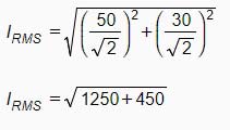
Ques.49. In a series RLC circuit R 20Ω, XL = 30Ω and Xc =30Ω. If the supply voltage across the combination is v = 100sin(100πt + 30° ) volts, the instantaneous current and the power factor of the circuit are respectively (SSC-2012)