Ques.81. In an electric heater, the metal case is connected to
- Phase wire
- Earth wire✓
- Neutral Wire
- None of these
In an electric heater, the metal case is connected to Earth wire. Sometimes due to short circuit or due to any other reason large amount of current flows in the circuit. This current produces excessive heat (Q = I2Rt) in the circuit and may cause fire as well. To prevent the damage of electrical appliances against this heating and fire a local earthing is provided just below the electric meter in the house. For this purpose, a thick copper wire is connected to the earth wiring. The other end of this copper wire goes 3 to 4 metros deep inside the earth and is connected to a thick copper plate (50 cm x 50 cm) buried with the mixture of water, salt, and charcoal. To keep the copper plate conducting the ground above the plate is made wet from time to time. In case of excessive current in the live wire, it comes to earth wire and passes through the earth. In order to work an electrical appliance like electric iron, electric kettle or a room cooler, we need two wires of the supply line, the live wire, and the neutral wire. Sometimes, due to wear and tear or due to excessive heating, the plastic covering (or insulation) of the connecting wires gets removed or gets burnt and the live wire (which is at a high potential of 220 volts) becomes naked. This naked live wire may touch the metal case (or metal body) of the electrical appliance due to which the case becomes live and comes to the high voltage of 220 volts. If we happen to touch any part of this live appliance, a very high current flows through our body into the earth Due to this high current flowing through our body we get an electric shock. To avoid the risk of electric shocks, the metal body of an electrical appliance is “earthed”. Earthing means to connect the metal case of the electrical appliance to the earth (at zero potential) by means of a metal wire called “earth wire”. in household circuits, we have three wires, the live wire, the neutral wire, and the earth wire. One end of the earth wire is buried in the earth. We connect the earth wire to the metal case of the electrical appliance by using a three-pin plug. The metal casing of the appliance will now always remain at the zero potential of the earth. We say that the appliance has been earthed or grounded. Let us make it more clear with the help of a diagram. The figure shows the earthing of an electric iron or press. The live wire and the neutral wire are connected to the two ends of the heating element whereas the earth wire is connected to the metal body of the electric iron. These three wires are connected to a three-pin plug P. The plug P is connected to a three-pin socket S. Let us see how the earth connection actually works. If by chance, the live wire touches the metal case of the electric iron (or any other appliance), which has been earthed, then the current passes directly to the earth through the earth wire. It does not need our body to pass the current and, therefore, we do not get an electric shock. Actually, a very heavy current flows through the earth wire and the fuse of household wiring blows out or melts. And it cuts off the power supply. In this way, earthing also saves the electrical appliance from damage due to excessive current. From the above discussion, we conclude that we earth the metallic body of an electrical appliance to save ourselves from electric shocks. Thus, the earthing of electrical appliances is used as a safety measure. It should be noted that we give earth connections to only those electrical appliances which have the metallic body, which draw heavy current, and which we are liable to touch. For example, electric iron, electric heater, room cooler, and refrigerator, are all provided with earth connections. We, however, do not do earthing of an electric bulb or a tube-light because we hardly touch them when they are on. Hence in the case of proper earthing no sooner the live wire touches the metal body than a large number of current flows in the body of nearly zero resistance and the fuse connected to the appliance blows off to disconnect the circuit. Clearly, the fuse has to be connected to the live wire.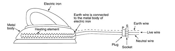
Ques.82. Which of the following is not indoor lighting?
- Residence lighting
- Office Light
- Flood Light✓
- Industry Light
The design of lighting systems can be separated between indoor and outdoor illumination systems. Indoor lighting systems can be divided into lighting for general areas such as walkways, manufacturing, and machine or process lighting, while outdoor lighting is primarily directed toward area lighting such as entryways to facilities’ parking and buildings. Interior lighting design is made more complex in that different surfaces reflect light at differing rates and different tasks require different levels of lighting. Flood Lighting Flood-lighting means Flooding of large surfaces with light from powerful projections. It is employed to serve one or more of the following purposes. It is usually installed outdoor and in an inaccessible position. Aesthetic flood-lighting: It is used for enhancing the beauty of buildings at night, ancient buildings and monuments, churches, gardens, etc industrial and commercial flood-lighting: It is used for illuminating railway yards, art stadiums, car parking areas, etc Advertising: It is used for illuminating advertisements and shows cases at night
Ques.83. Carbon arc lamps are commonly used in
- Domestic Lighting
- Street Lighting
- Cinema projector✓
- Photography
Carbon arcs operate by ionizing air molecules (which carry the current between the carbon electrodes) to incandescence. To ignite the lamp, the rods are touched together, thus allowing a relatively low voltage to strike the arc. The rods are then slowly drawn apart, and electric current heats and maintains an arc across the gap. The tips of the carbon rods are heated and the carbon vaporizes. The carbon vapor in the arc is highly luminous, which is what produces the bright light. The rods are slowly burnt away in use, and the distance between them needs to be regularly adjusted in order to maintain the arc. The carbon arc lamp was mainly used in the cinema projector. A carbon electrode projector produces the best possible light, a pure white with even brightness. But the rods are consumed in less than an hour (another reason for changeovers), and their burning produces carbon monoxide. The carbon-arc played a significant role until the introduction of the short-arc xenon discharge lamp in 1951.
Ques.84. Lumen/watt is the unit of
- Light flux
- Luminous intensity
- Brightness
- Luminous efficiency✓
The luminous efficiency of an electric lamp is the ratio of the luminous flux (in Lumen) emitted by the lamp to the electric power (in watt) given to it i.e η = Luminous flux (in Lumen) emitted by the lamp ⁄ Electric power (in watt) It is clear that the luminous efficiency of the electric lamp is measured in Lumen/Watt
Ques.85. Arc can be produced by?
- AC current only
- DC current only
- Either AC or DC current✓
- All option are correct
An electric arc is a visible plasma discharge between two electrodes that is caused by electrical current ionizing gasses in the air. Electric arcs occur in nature in the form of lightning. With proper control, electric arcs can be harnessed and used industrially for welding, plasma cutting, and even certain types of lighting such as fluorescent lighting where a high voltage ionizes the inert gas within a glass tube; the flow of current across the ionized gas liberates visible light. An arc is generated between two conductors of electricity, cathode, an anode (Either AC or DC) when they are touched to establish the flow of current and then separated by a small distance. An arc is a sustained electric discharge through the ionized gas column called plasma between the two electrodes. The electron is negatively charged are attracted towards the positive contact(i.e anode) with a high velocity and on the way they detach more electrons by impacts. The positive ions are4 attracted towards the negative contacts (i.e cathode), but as they comprise almost the entire weight of the atom, they move towards it relatively slowly. This current flow is caused due to the movement of electrons. In order to produce the arc, the potential difference between the two electrodes (voltage) should be sufficient to allow them to move across the air gap. The larger air gap requires a higher potential difference. If the air gap becomes too large for the voltage, the arc may be extinguished.
Ques.86. A rectifier for welding has voltage/current characteristics as
- Drooping✓
- Rising
- Static
- Variable
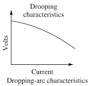
Rectifier for welding consists of a transformer (single-or three-phase) and a rectifier unit as shown in Fig. Such a unit has no moving parts, hence it has a long life. The only moving part is the fan for cooling the transformer. But this fan is not the basic part of the electrical system. Fig. shows a single-phase full-wave rectifier circuit of the welder. Silicon diodes are used for converting a.c. into d.c. These diodes are hermetically sealed and are almost ageless because they maintain rectifying characteristics indefinitely. Such transformer-rectifier welding is most adaptable for shied arc welding because it provides both d.c. and a.c. polarities. It is very efficient and quiet in operation. These welders are particularly suitable for the welding of The open-circuit voltage of a constant-current, rectifier type power source ranges from about 50 to 100 V hence it provides the highest potential voltage when the welding current circuit is open and no current is flowing. At the start of the weld, with striking the arc, the sharp drop in voltage takes place from the OCV. A conducting column of ionized gases is formed along with the heating up of the electrode. As there is a drop in voltage, the simultaneous increase in welding current takes place. After a certain point, the voltage/current variation becomes linear following Ohm’s law. The static volt-ampere characteristics of a welding power source are shown in Fig. 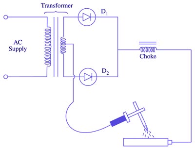
Ques.87. The insulating material suitable for low-temperature applications is
- Cork✓
- Diatomaceous Earth
- Asbestos Paper
- 75% magnesia
Note:- The option was wrong in the paper (Diatomaceous Earth) even many another website provide the wrong answer so don’t get confused. Cork is the bark of the Cork Oak tree. It is a completely natural raw material, with unique properties which give it an unrivaled character. It is light, impermeable to liquids and gases, elastic and compressible, provides thermal and acoustic insulation, it is a fire retardant, and is highly abrasion-resistant. Furthermore, it is completely biodegradable, renewable, and recyclable. Cork has long been used for low-temperature insulation because it has a high resistance to heat flow. This property is largely due to the fact that cork is a cellular material, and each of the cells contains air. Air is one of the best-known insulators, and any material that contains small air cells is a good insulator. The same protective principle can also be found in other natural products, such as wool and feathers. The more thoroughly the air is confined, the better are the insulating characteristics. Many so-called dead-air spaces actually allow the circulation of air to the extent that their value is reduced. Diatomite, or diatomaceous earth, erroneously called infusorial earth, is actually not earthy but an opaline mineral composed principally of silica and consisting chiefly of the fossil remains of aquatic plant organisms known as diatoms. kieselgur/kieselguhr is the Gennan term formerly used in this country. The pure varieties of diatomite are chalk-like (white powder) in appearance; impurities may cause greenish, brown, or gray color. Impurities like calcium oxide and iron oxide are found in the diatomaceous earth. It is used as a filtration aid, mild abrasive in products including metal polishes and toothpaste, mechanical insecticide, absorbent for liquids, matting agent for coatings, reinforcing filler in plastics and rubber, anti-block in plastic films, porous support for chemical catalysts, cat litter, activator in blood clotting studies, a stabilizing component of dynamite, and a thermal insulator(900° C). It is suitable for high-temperature applications.
Ques.88. The method suitable for heating of conducting medium is
- Induction Heating✓
- Indirect heating
- Eddy current heating
- Radiant heating
The method suitable for heating of conducting medium is induction heating. Induction heating is defined as the process of heating an electrically conducting object (usually a metal) by electromagnetic induction, through heat generated in the object by eddy currents. In induction heating when an alternating voltage applied to an induction coil (e.g., solenoid coil) will result in an alternating current in the coil circuit. An alternating coil current will produce in its surroundings a time-variable magnetic field that has the same frequency as the coil current. That magnetic field strength depends on the current flowing in the induction coil, the coil geometry, and the distance from the coil. The changing magnetic field induces eddy currents in the workpiece located inside the coil. These induced currents have the same frequency as the coil current; however, their direction is opposite to the coil current. Alternating eddy currents induced in the workpiece produce their own magnetic fields, which have opposite directions to the direction of the main magnetic field of the coil. Therefore, the total magnetic field of the induction coil is a result of the source magnetic field and induced magnetic fields. Alternating eddy currents produce heat by the Joule effect (I2R). A conventional induction heating system that consists of a cylindrical load surrounded by a multiturn induction, the coil is shown in Figure. In a narrow sense, induction heating is similar to the Joule heating effect, but with one important modification. The currents that heat the material are induced via electromagnetic induction. Therefore, it could be a non-contact heating process. Accordingly, only those with high electric conductivity, such as copper, gold, and aluminum, can be directly heated via induction. Food items are then heated by the metals. Induction heating works better on specific metals due to additional heating mechanisms. For instance, induction can heat ferrous metals better than other materials. That is because the iron crystals in ferrous metals can be repeatedly magnetized and demagnetized by the alternating magnetic field. This will lead to hysteresis losses in addition to the normal induction heating.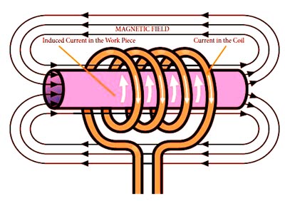
Ques.89. The number of valence electrons in boron is
- 5
- 3✓
- 2
- 1
In chemistry, a valence electron is an outer shell electron that is associated with an atom, and that can participate in the formation of a chemical bond if the outer shell is not closed. Boron is the first member of the elements of group 13 of the periodic table. It is the only non-metal of this group. It has three electrons in the valence shell. It is also known as the acceptor impurity.
Ques.90. The potential barrier acts as a barrier against the flow of
- Electrons Only
- Holes only
- Electrons and holes✓
- None of the above
Consider a semiconductor bar consisting of a PN junction. Assume that the entire sample is a single crystal and the PN junction is just formed. The left half section of the semiconductor bar is a P-type and the right half-section of the semiconductor bar is N-type. The P-type region consists of majority carriers (holes) and negatively charged acceptor ions (negative ions). The N-type region contains majority carriers (electrons) and positively charged donor ions (positive ions). The minority carriers in the P-type and N-type regions are ignored. The figure shows the formation of the depletion layer in a PN junction when no external voltage is applied to the PN junction. Just after the formation of the PN junction, the conduction and valence bands of P-type and N-type semiconductor materials overlap, and the following processes take place. 1. The P-type region has more holes and the N-type region has more free electrons. There is a difference of concentrations in the P-type region and N-type region. The difference in concentration generates a concentration gradient across the junction. Therefore, there is a diffusion of mobile charge carriers across the junction. 2. The electrons and holes can move at random in all directions due to thermal agitation. Therefore, some carriers are able to cross over the junction. 3. The holes will diffuse to the N-type region from the P-type region and combine with the free electrons. 4. The free electrons will diffuse to the P-type region from the N-type region and they combine with holes. 5. The diffusion of holes and free electrons across the junction takes place for a short time. After recombination of holes and free elections, a limiting force is developed. Due to this force, the depletion layer stops further diffusion of holes and free electrons from one region to the other region. Just after the formation of the PN junction, the holes in P-type region and the free electrons in the N-type region will diffuse with each other and disappear due to recombination. Therefore, the negative acceptor ions in the P-type region and positive donor ions in the N-type region are left uncovered in the junction region. Some holes will diffuse to the N-region and they are replaced by the uncovered positive charge of the donor ions. In the same way, some electrons will diffuse into the P-type region and are replaced by the uncovered negative charge of the acceptor ions. After the initial diffusion of free electrons and holes, their further diffusion across the junction is stopped. Consequently, a region that consists of the uncovered acceptor and donor ions is developed in the junction area. This region is called the depletion region, as shown in Fig. As the depletion region consists of immobile positive and negative ions, it is called the space-charge region. Since the uncovered charges within the depletion region exist in the form of parallel rows of opposite charges, it is also called the depletion layer. The depletion layer behaves just like an insulator. Due to the presence of rows of fixed charges, the depletion layer develops a capacitance. The width of the depletion layer depends upon the doping level of the impurity in N-type and P-type semiconductors. When the doping level is high, the thinner depletion layer will be developed and vice versa. The reason for the thinner depletion layer is that the highly doped PN junction contains a large number of electrons and holes and diffusing charge carriers (free electron or hole) cannot cross the junction for recombination. The electrons and holes recombine near the junction and thus cancel each other out. This results in opposite charges of each side of the junction, creating a depletion region, or space charge region. The depletion layer in semiconductors acts as a barrier that opposes the flow of electrons from the n-side and holes from the p-side. To overcome this barrier potential, we need to apply an external voltage that is greater than this barrier potential. When the voltage applied to the p-n junction diode is greater than the barrier potential, the electric current starts flowing. The potential difference created across the P-N junction due to the diffusion of electrons and holes is called a potential barrier. For Ge VB = 0.3 V and for silicon VB = 0 7 VPN junction Depletion Region and Potential Barrier