Ques.51. The loss associated with the mechanical friction of a machine is called
- Eddy current Loss
- Mechanical Loss✓
- Hysteresis Loss
- Stray Load loss
In the rotating machine whether it is AC or DC machine the type of losses are almost the same The various losses in a d.c. the machine, whether it is a motor or a generator, is categorized amplified into three groups as: Copper losses are also called Electrical losses, winding losses or Ohmic losses. The copper losses are the losses taking place due to the current flowing in a winding. There are basically two windings in a d.c. machine namely armature winding and field winding. The copper losses are proportional to the square of the current flowing Through these winding; Thus the various copper losses can be given by Core losses are also known as iron losses or Magnetic losses. These Losses are constant and independent of the load. They are induced in the machine due to hysteresis and eddy currents produced in the core produced when the magnetization is changing. They mainly occur in the armature teeth and core as also in the pole shoe. Hysteresis losses occur due to the reversal of the magnetization of the armature core. So, the hysteresis loss can be obtained as: Hysteresis Loss = Kh × BM1.67 × f × v watts where The eddy current loss exists due to eddy currents. When the armature core rotates, it cuts the magnetic flux and e.m.f. gets induced in the core. This induced e.m.f. sets up eddy currents which cause the power loss. Ibis loss is given by, Eddy current losses = Ke × Bm2 × f2 × t2 Where Ke = Eddy current constant These losses are produced due to friction and windage (friction with air) caused by machine rotation. Hence, these are named mechanical losses. Some power is required to overcome mechanical friction and wind resistance at the shaft. They depend on the speed of the machine. The mechanical losses are also constant for a d.c. machine Bearing friction loss generally depends on the type of bearing used and on the viscosity of the lubricant. Brush friction loss is proportional to the contact area and the brush pressure. It also depends on other factors like the material of the brush and commutator, their polish condition, and the temperature at the contact surface. The magnetic and mechanical losses together are called stray losses. Stray load losses are losses that are produced in the machine when they are loaded. They cannot be considered with the main losses listed above. These losses include: (a) Additional core loss resulting from armature reaction distortion. (b) Copper loss due to short circuits produced in coils, segments, and brushes during commutation. (c) Copper loss due to non-uniform distribution of current in large-sized armature conductors. Stray load losses are very small in value and therefore, they are very difficult to calculate. In small machines, they can be neglected but for large machines, they are generally considered to be 1% of the output power in total.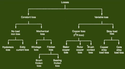
Copper Losses
Core Losses
Kh = Hysteresis constant depends upon the material
Bm = Maximum flux density
f = frequency
v = Volume of the core
t = thickness of the coreMechanical Losses
Stray Load Losses
Ques.52. For a 3-phase load-balanced condition, each phase has the same value of
- Impedance
- Resistance
- Power factor
- All option are correct✓
These are some of the terms used while describing a three-phase system. These are:
Ques.53. A short-circuit test on a transformer gives
- The copper loss at full load
- The copper loss at any load✓
- The copper loss at half load
- The copper loss at overload
Short circuit test or Impedance test is performed to determine Normally the short circuit test is performed on HV winding by short-circuiting the LV winding because if we perform a test on the low voltage side a very high current is going to flow so to measure this huge current will need a large measuring instrument such as an ammeter. Therefore, the TEST of the short circuit is done on the high voltage side, which equivalently meant low current(a transformer is a constant power device). So the maximum current won’t be more than some 5-50 ampere and can be easily measured. The SC test can be done on either side and will be reflecting the same results, but it is always recommended to work safely, thus shorting the HV side, is the safest way. With one winding short-circuited, typically 10% of rated voltage on the other winding is sufficient to establish rated full load current. For convenience, we will short the secondary winding, take measurements in the primary winding and refer to the secondary quantities as appropriate. Measure: Vsc short-circuit primary voltage { Very low as compared to the rated voltage Isc short-circuit primary (rated) current { comparable to full load current} Psc short-circuits power (measured with a wattmeter). The short circuit voltage is very low as compared to the rated voltage so if the voltage is very low the loss related to the voltage i.e core loss will also be very less. Hence the core loss is neglected in the short circuit test. Since the high current is passing through the winding, therefore, wattmeter will only read the copper loss. For SC test Power Losses Psc = I2ScRs Where I2Sc = Short circuit current RS = Secondary winding resistance Impedance Zs = VSc ⁄ ISc The copper losses depend upon the loading conditions of the transformers. The copper losses depend on the magnitude of the current flowing through the windings. As the load on the transformer is not constant, the copper loss is called variable loss If the current through the windings is full load current, we get copper losses at full load. If the load on the transformer is half then we get copper losses at half load which is less than full load copper losses. Thus copper losses are called variable losses. Therefore we can determine copper loss at any load.
⇒ Copper loss at any load
⇒ Equivalent impedance (Zo1 or Zo2)
⇒ Leakage reactance (Xo1 or Xo2)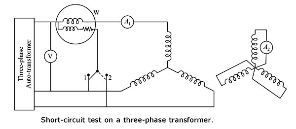
Ques.54. Armature reaction effect causes the flux to reduce with
- Decreasing Torque
- Increasing Torque
- Increasing current✓
- Both Increasing torque and increasing current
The armature reaction effect causes the flux to reduce with increasing current. When the load is connected to the DC motor, the armature winding of the DC motor carries a current. Every current-carrying conductor produces its own flux so the armature of the DC motor also produces its own flux when carrying a current. So there are two fluxes present in the air gap, one due to armature current while the second is produced by the field winding called main flux. The flux produced by the armature is called armature flux So the effect of the armature flux on the main flux affects its value and the distribution is called armature reaction. The armature reaction always results in the reduction of generated e.m.f due to a decrease in the value of flux Per Pole. Armature reaction occurs in DC motors and is caused by the stator magnetic field being distorted, or altered, in reaction to the armature magnetic field. The armature reaction is actually a bending of the motor magnetic field so that the brushes are no longer aligned with the neutral magnetic plane of the motor. If the brushes are not in alignment with this magnetic plane, the current conducted to the armature does not split equally in the armature conductors and therefore causes a voltage difference at the brushes. This causes sparking where the brush meets the commutator. In a motor with a constant load. We know that reducing the flux leads to an increase in speed, so we can now see that in a machine with a pronounced armature reaction, when the load on the shaft is increased and the armature current increases to produce more torque, the field is simultaneously reduced and the motor speeds up. Though this behavior is not a true case of instability, it is not generally regarded as desirable! Large motors often carry additional windings fitted into slots in the pole-faces and connected in series with the armature. These ‘compensating’ windings produce an m.m.f. in opposition to the armature m.m.f., thereby reducing or eliminating the armature reaction effect.
Ques.55. The armature of a DC machine is made of
- Mild Steel
- Silicon Steel✓
- Stainless steel
- Cast Iron
The armature winding of the DC motor is connected to a rotating part of the machine called the rotor. It goes through an alternating magnetic field. This results in magnetic losses. Because of magnetic losses, the rotor is built using an armature core which in turn is made with much low-hysteresis silicon steel lamination. These laminations are stacked together to create a cylindrical structure thus providing a high resistance path to the eddy currents hence less heat is generated. Hence hysteresis and eddy current losses are reduced by using the silicon steel
Ques.56. DC generators are designed to develop armature voltages not exceeding 650 V because of the limitations of
- Field winding
- Armature Winding
- Commutator✓
- Starter
The armature is rotating in nature in the case of DC machines. We can’t keep armature on stator like in case of Alternators. In high voltage DC Generators, there is not enough space to keep heavy armature windings on the rotor. In DC machines commutator is present which is absent in AC Generator. In the construction of a commutator, there are a number of Copper segments that are insulated from each other by the thin sheet of mica or other insulation material. The number of commutator segments must be equal to the number of coils in the armature. If the generated voltage is high in DC Generator the insulation required will be more in the commutator and the size of the commutator will increase along with the armature. Such a commutator becomes heavy in weight. As the DC generator has brushes and commutators, there is sparking in the assembly and also due to the friction between the brush and commutator, there is more requirement of maintenance. Hence, they are not robust and need frequent maintenance, unlike the AC generators, which don’t have any such parts and the power is directly taken from the steady windings of the stator.
Ques.57. A step-up transformer increases
- Power
- Voltage✓
- Frequency
- Current
When the secondary voltage is greater than the primary voltage it is called as a step-up transformer. The function of the step-up transformer is to increase the voltage level. On a step-up transformer, there are more turns on the secondary coil than the primary coil.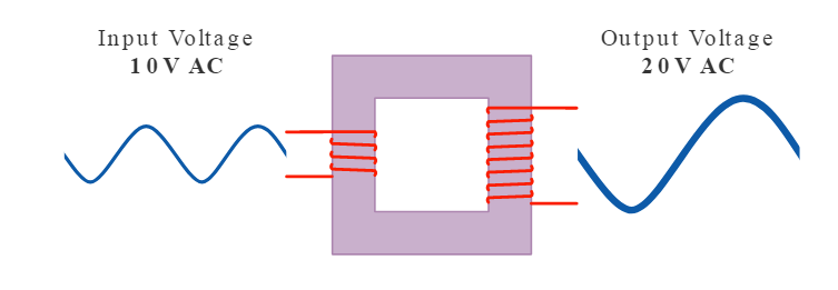
Ques.58. It is economical to transmit electricity at a
- Very high voltage✓
- Very low voltage
- Very high current
- None of these
Advantages of High Voltage Transmission
Ques.59. Rotating magnetic fields are also used in 3-phase induction motors rotor developing
- Eddy current✓
- Voltage Lag
- Load current
- Phase current
The polyphase induction type of motor depends upon the principle of a rotary magnetic field. Polyphase motors using a rotating magnetic field were invented by Nikola Tesla in 1898. When a rotating magnetic field is subjected to a metallic cylinder free to rotate in the field, eddy currents are set up in it. These currents, according to Lenz’s law, try to reduce the relative motion between the cylinder and the field. Therefore the cylinder begins to rotate in the direction of the field. This principle is used in induction motors. Let us explain in detail The rotating magnetic field can be defined as the field or flux having constant amplitude but whose axis is continuously rotating in a plane with a certain speed. So if the arrangement is made to rotate a permanent magnet, then the resulting field is a rotating magnetic field. But in this method, it is necessary to rotate a magnet physically to produce a rotating magnetic field. But in three-phase induction motors, such a rotating magnetic field is produced by supplying currents to a set of stationary windings, with the help of three-phase a.c. supply. The current-carrying windings produce the magnetic field or flux. And due to the interaction of three fluxes produced due to three-phase supply, resultant flux has a constant magnitude and its axis rotates in space, without physically rotating the windings. This type of field is nothing but a rotating; magnetic field. A 3-phase induction motor mainly consists of two major parts, the stator and the rotor separated by a uniform air gap. When the 3-phase winding suitably wound on the stator is supplied with a 3-phase balanced ac supply, a uniformly rotating magnetic field of constant magnitude and rotating at synchronous speed is produced. The rotor of an induction motor is placed in a rotating magnetic field. The speed of this rotating magnetic field is known as the synchronous speed (N,). The lines of force of the stator rotating magnetic field cut the rotor conductors and as a result, an alternating emf is induced in these conductors. Due to the relative motion between the rotating magnetic field and the rotor, a voltage is induced in the conductors placed on the rotor. Since the conductors on the rotor form a closed path due to short-circuited end rings (in cage type of rotor) or through external resistance via slip rings (in case of wound rotor) hence the rotor winding for both types of 3-phase induction motors is equivalent to a short-circuited winding The rotating magnetic field developed by the AC current flowing in the stator windings induces a current in the rotor. Due to this the short-circuited turns of the rotor develop eddy currents in the rotating field of the stator. The interaction of the two magnetic fields turns the rotor and drives the motor shaft firmly attached to the rotor by Lorentz force. It is obvious that the rotor speed cannot become equal to the synchronous speed because, in that case, there will be no relative motion between the rotating magnetic field and the rotor, resulting in no induced current in the rotor conductors, and no torque acting on the rotor. Then, the rotor tends to retard. Therefore, there will always be a slight difference between synchronous speed N1 and the speed of the rotor N2.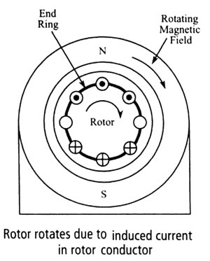
Ques.60. One of the speed control methods of a 3 phase induction motor is
- V/F control✓
- Stator current control
- Core loss control
- Eddy current Control
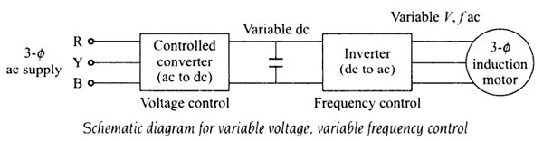
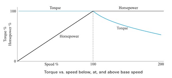
An induction motor on a normal supply operates with a rotating field set up by three-phase currents in the stator winding. The magnitude of the field is controlled broadly by the voltage impressed upon the winding by the supply. This is because the resistance of the winding results in only a small voltage drop, even at full-load current, and therefore in the steady-state the supply voltage must be balanced by the e.m.f. induced by the rotating field. This e.m.f. depends on the product of three factors: Synchronous speed, therefore, the motor speed can be controlled by varying supply frequency. The voltage induced in the stator is proportional to the product of supply frequency and air-gap flux. If stator drop is neglected, the terminal voltage can be considered proportional to the product of frequency and flux. V = φF And also the torque of an induction motor is directly proportional to the flux T ∝ φ ∝ V/F Hence for the same design parameters [φ remaining the same] and ratio V/F, the torque of the motor, T, will remain constant. Since both V and f, are functions of the supply system, a variation in V and f can alter the performance and the speed-torque characteristics of a motor as required, at constant torque. The variable frequency, variable voltage supply required in this method of speed control, can be obtained by using a controlled converter and an inverter in between the 3-phase supply and the 3-phase induction motor, as shown in Fig. The controlled converter, rectifies the 3-phase, ac supply of standard frequency and voltage to a dc of variable voltage. The voltage can be varied, as per the requirement of the frequency variation. The de variable voltage is inverted to 3-phase, AC with variable frequency, variable voltage by a 3-phase inverter. The frequency control is obtained by the inverted. Thus, with the above circuit, it is possible to obtain a variable frequency, the variable voltage source with V/f constant. to be applied to the 3-phase induction motor. Increased Voltage If in the steady-state, the voltage applied to the stator terminals is increased without a corresponding increase in the frequency, only the flux can vary to regain the balance between applied voltage and e.m.f. If the flux is forced to increase by applying excessive voltages, the iron core of the machine is driven progressively into saturation. This not only increases iron losses due to hysteresis and eddy currents but can lead to a very marked increase in stator current, with corresponding resistive losses. Since most machines are designed to work with the minimum of material, their magnetic circuits are normally very close to saturation and excessive stator voltage is a condition that must be carefully avoided. Reduce frequency Any reduction in the supply frequency, without a change in the terminal voltage, causes u increase in the air-gap flux. Induction motors are designed to operate at the Knee point of the magnetization characteristic to make full use of the magnetic material. Therefore, the increase in flux will saturate the motor. This will increase the magnetizing current, distort the line current and voltage, increase the core loss and the stator copper low, and produce a high-pitch acoustic noise. Base Speed Base speed,” is defined as the speed at which the motor will first produce its maximum designed power output, and “maximum speed,” the fastest the motor can spin while producing that same amount of power (available torque falls off as speed increases past “base speed.”) Operation above base speed First, operation above base speed is easily achieved by increasing the output frequency above the normal mains frequency since the rise in the applied voltage is not permitted beyond the rated voltage, which has already been attained by reaching the rated speed. The speed beyond the rate is therefore obtained by raising the supply frequency alone and maintaining the voltage at constant as it rated value. Since V is constant above base speed, the flux will fall as the frequency is increased after the output voltage limit is reached. The machine flux falls in direct proportion to the actual V/f ratio. Although this greatly reduces the core losses, the ability of the machine to produce torque is impaired and less mechanical load is needed to draw full-load current from the inverter. The drive is said to have a constant power characteristic above base speed. Many applications not requiring full torque at high speeds can make use of this extended speed range. Operation below base speed Each AC induction motor is designed to run at a particular RPM, called base speed. When power is applied, the motor accelerates from 0 RPM. As it does, the torque remains constant and the horsepower increases until the base speed is reached. Above base speed, the torque falls off while the horsepower remains constant. Below the base speed (V/F ratio is maintained constant, except at low frequencies where (V/f ) ratio is increased to keep maximum torque constant. By maintaining a constant ratio of voltage to speed, we can maintain a constant air gap flux. Because torque is proportional to air gap flux, hence by constant V/f ratio, the torque can be made independent of speed in an AC motor. Hence we can achieve constant torque down to very low speeds. Example One example is a paper winder. When it begins to wind, the empty core is light and does not require much torque to turn. Therefore, it can be turned above base speed at reduced torque. As the roll is being wound and becomes heavier, the torque required to turn it becomes greater. Therefore, it is necessary for the driver to slow the speed and eventually run below the base speed so that torque is increased to handle the load. Eventually, the roll is heavy and requires the motor to provide maximum torque.
and φ = V/F