
Ques.61. The starting torque of a 1-phase induction motor is
- High
- Moderate
- Low
- Zero✓
The working principle of an ac machine is primarily “one field following another field”. In the case of a multiphase induction motor, there will be a virtual rotating magnetic field. But considering the case of a single-phase induction motor, it’s only a pulsating field that is produced and not a rotating one. This can also be explained on the basis of ‘DOUBLE REVOLVING FIELD THEORY‘, which is based on Ferraris Principle As per Ferrari’s principle, the alternating magnetic field produced by the stator can be split into two rotating magnetic fields of half the magnitude and rotating at synchronous speed in opposite directions. When the alternating supply is fed to the stator winding, an alternating flux is developed This flux rotates and cuts the rotor conductors. Due to this, an EMF is induced. As the rotor circuit is closed the current flows through the rotor conductor. This rotor current will cause rotor flux and at any instant, its magnitude is given by, φs = φm COS ωt where φm is the maximum flux developed in the motor. According to this theory, the alternating flux φs can be resolved into two components of and φf & φb such that the magnitude of by φf & φb is equal to half the magnitude of φs . Let us assume that φf rotates in a clockwise direction and φb rotates in the anti-clockwise direction. An emf is induced in the rotor circuit due to each rotating field. If the polarity of the induced emf in the rotor due to φf is taken as positive then emf induced in the rotor due to φb is negative (i.e. in phase opposition). As, at standstill, the slip in either direction is the same (i.e. s = 1), the rotor impedance will also be the same. Thus, the rotor currents are equal, but opposite in phase that is the starting torque developed by each revolving field is the same, with one acting in forwarding direction and the other acting in the backward direction. Thus, the net torque developed by the motor is zero. Based on double-revolving field theory, a single-phase induction motor can be visualized as having two rotors revolving in opposite directions with a common stator winding. At standstill, the two rotors develop equal torques in opposite directions and hence the net torque developed is zero.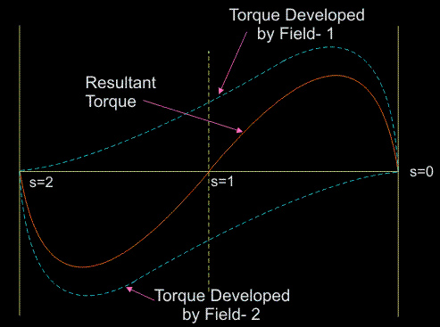
Ques.62. In a shaded pole single-phase motor, the revolving field is produced by the use of
- Inductor
- Capacitor
- Resistor
- Shading coils✓
The Shaded-pole motor has a salient pole stator similar to the stator of dc machine. The pole is laminated to reduce the core losses. The pole is physically divided into two sections as shown in the figure. A heavy, short-circuited copper ring, called the shading coil, is placed on the smaller section of the pole. This section covers around one-third of the pole arc and is called the shaded portion of the pole. The remaining two-thirds section of the pole is referred to as the unshaded portion. The main single-phase winding is wound on the entire pole section. The rotor used is similar to the rotor of any other single-phase induction motor. When a single-phase supply is fed to the main winding, an alternating flux is produced in the pole. A portion of this flux links with the shading coil and induces a voltage in it. As a shading coil is a short-circuited coil, a large current flows in it. The current in the shading band causes the flux in the shaded portion of the pole to lag the flux in the unshaded portion of the pole. Thus the flux in the shaded portion reaches its maximum value after the flux in the unshaded portion reaches its maximum. This is equivalent to a progressive shift of the flux from the unshaded to the shaded portion of the pole, that is it is similar to a rotating field moving from the unshaded to the shaded portion of the Pole. Hence. the motor reproduces a starting torque. Because of the small phase of displacement of the currents in the main and the auxiliary winding and because of the winding misalignment lower than π/2 the start torque is very low. The shaded pole motor efficiency suffers greatly due to the presence of winding harmonic content, particularly the third harmonic which produces a dip in the speed-torque curve at approximately 1/3 synchronous speed. In addition, there are losses in the shading coils. These factors combine to make the shaded pole the least efficient and noisiest of the single-phase designs. It is used mostly in air moving applications where its low starting torque and the third harmonic dip can be tolerated. Some important Points of shaded Poles Motor Therefore shaded-pole motors are especially suited for small fans and pumps. Other applications are juice presses, clothe dryers, grills, simple butterfly control waves, massage apparatus, hot-air stoves, and cabinet fans. Drives for reversing duties can be built with two motors assembled homologously. Shaded-pole motors are low-cost motors. Because of their low efficiency, they mostly need intensive cooling.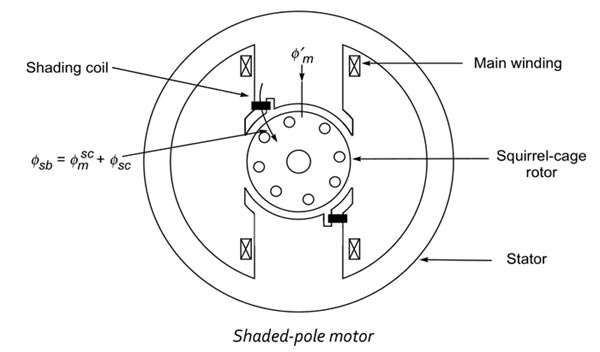
Ques.63. The repulsion-start induction-run motor is used because of
- Good Power factor
- High Efficiency
- Minimum cost
- High starting torque✓
A repulsion motor operates on the principle that magnetic poles repel each other, not on the principle of a rotating magnetic field. The stator of a repulsion motor contains only a run winding very similar to that used in the split-phase motor. Start windings are not necessary. The rotor is actually called an armature because it contains a slotted metal core with windings placed in the slots. The windings are connected to a commutator. A set of brushes makes contact with the surface of the commutator bars. The entire assembly looks very much like a DC armature and brush assembly. One difference, however, is that the brushes of the repulsion motor are shorted together. Their function is to provide a current path through certain parts of the armature, not to provide power to the armature from an external source. Operation Although the repulsion motor does not operate on the principle of a rotating magnetic field, it is an induction motor. When AC power is connected to the stator winding, a magnetic field with alternating polarities is produced in the poles. This alternating field induces a voltage into the windings of the armature. When the brushes are placed in the proper position, current Hows through the armature windings, producing a magnetic field of the same polarity in the armature. The armature magnetic field is repelled by the stator magnetic field, causing the armature to rotate. Repulsion motors will contain the same number of brushes as there are stator poles. Repulsion motors are commonly wound for four, six, or eight poles. Repulsion-Start Induction-Run Motor The repulsion-start induction motor, exactly like a repulsion motor, is capable of developing high starting torque At about 75 percent of synchronous speed, a centrifugally operated device short-circuits the entire commutator. From this speed onwards, the motor behaves like an induction motor. After the commutator is short-circuited, brushes do not carry any current, hence they may also be lifted from the commutator, in order to avoid unnecessary wear and tear and friction losses. Repulsion-start motors are of two different designs: 1. Brush-lifting type in which the brushes are automatically lifted from the commutator when it is short-circuited. These motors generally employ the radial form of the commutator and are built both in small and large sizes. 2. Brush-riding type in which brushes ride on the commutator at all times. These motors use an axial form of the commutator and are always built-in small sizes. The torque developed is proportional to the product of the stator flux and rotor current. Rotor current depends on the stator flux and stator flux is proportional to the stator current. Therefore, the torque developed by a repulsion motor is proportional to the square o the staler current. Since the torque developed is proportional to the square of the stator current, the torque-speed characteristics of a repulsion motor are high. The magnitude of starting torque of a repulsion motor is high. The magnitude of starting torque depends on the position of the brush axis. Its speed regulation, like a series motor, is poor. The starting torque of such a motor is in excess of 350 percent with a moderate starting current. It is particularly useful where the starting period is of comparatively long duration, because of high inertia loads. Applications of such motors include machine tools, commercial refrigerators, compressors, pumps, hoists, floor-polishing and grinding devices etc. The disadvantage is:- noisy performance, poor speed regulation, and periodic commutator maintenance refinement. Because of the disadvantages mentioned above, repulsion motors have largely been replaced by capacitor-type motors and very few repulsion motors are manufactured.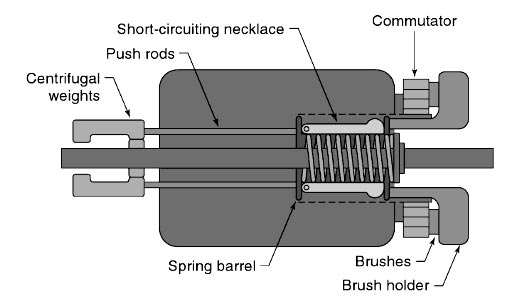
Ques.64. The rotor slots, in an induction motor, are usually not quite parallel to the shaft because of it
- Improves the efficiency
- Helps the rotor teeth to remain under the stator teeth
- Helps in reducing the tendency of the rotor teeth to remain under the stator teeth✓
- Improves the power factor
The rotor bars are not exactly parallel to the shaft but are given a slight skew. This skew helps to make the motor run quietly by reducing the magnetic hum. Another advantage is that this skew reduces the locking tendency of the rotor. Rotor conductors are skewed because of the following main reasons Crawling:– Crawling is a phenomenon where harmonic components introduce oscillations in torque. With the bar skewed, the amount of the bar cutting the field line grows continuously and the next bar starts cutting the field lines as the first finishes. Due to this, we get Uniform Torque.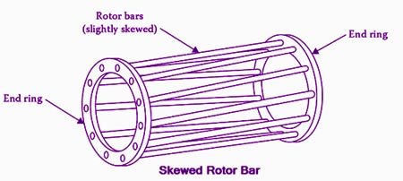
Ques.65. A shaded pole motor can be used for
- Toys
- Hair Dryers
- Circulators
- Any of the above✓
Some important Points of shaded Poles Motor Therefore shaded-pole motors are especially suited for small fans and pumps. Other applications are juice presses, clothe dryers, grills, simple butterfly control waves, massage apparatus, hot-air stoves, and cabinet fans. Drives for reversing duties can be built with two motors assembled homologously. Shaded-pole motors are low-cost motors. Because of their low efficiency, they mostly need intensive cooling.
Ques.66. The rotor of a hysteresis motor is made of
- Aluminum
- Cast Iron
- Chrome Steel✓
- Copper
Hysteresis motor is the synchronous motor that does not require any d.c. excitation to the rotor and it uses non-projected poles. Hysteresis motors start by virtue of the hysteresis losses induced in the rotor by the rotating magnetic field produced by the stator windings. It consists of a stator that carries main and auxiliary windings so as to produce a rotating magnetic field. The stator can also be shaded pole type. The rotor is the smooth cylindrical type made up of hard magnetic material like chrome steel or alnico for high retentivity (it is the capacity of an object to retain magnetism after the action of the magnetizing force has ceased. This requires selecting a material with a high hysteresis loop area. The rotor does not carry any winding.
Ques.67. The main advantage of AC transmission system over DC transmission system is
- Easy transmission
- Less losses in transmission over long distance✓
- Less insulation problem
- Less problem of instability
Generation, Transmission, and Distribution systems are the main components of an electric power system. Generating stations and distribution systems are connected through transmission lines. Normally, transmission lines imply the bulk transfer of power by high-voltage links between main load centers. On the other hand, the distribution system is mainly responsible for the conveyance of this power to the consumers by means of lower voltage networks. Electric power is generated in the range of 11 kV to 25 kV, which is increased by stepped-up transformers to the main transmission voltage. Electric Power can either be transmitted by means of AC or DC. Each system has its advantages and disadvantages. Therefore it is very crucial to have a comparative study of their merit and demerits and then decide which method should be adapted to transmit power. ALTERNATING CURRENT (A.C.) An alternating current is one that periodically changes in magnitude and direction. It increases from zero to a maximum value, then decreases to zero and reverses in direction, increases to a maximum in this direction, and then decreases to zero. The complete set of variations is known as a ‘cycle’. Thus during one-half of the cycle, the current flows in one direction, and in the following Cycle, it flows in the opposite direction. DIRECT CURRENT (D.C.) DC current is that current that may or may not change in magnitude but it does not change its direction. It is worthwhile to give advantages of ac. and d.c. Advantages of a.c. over d.c. Note:- There’s nothing inherently wrong with using DC for high-voltage long-distance power transmission, but there are some particular characteristics that sometimes make AC transmission more attractive. If the high cost of converter stations is excluded, the dc overhead lines and cables are less expensive than ac overhead lines and cables. Until the eighties, only AC was easy to step up or down as voltages, simply using transformers. Since then, advances in power semiconductors and microprocessor controllers have allowed DC to be easily converted to higher or lower voltages. But most high voltage power lines remain AC because it seems to be difficult to change the whole systemA.C. VERSUS D.C.
ADVANTAGES OF A.C OVER DC
Ques.68. Next lower voltage line feeding areas on either side of the main transmission line are called
- Secondary transmission✓
- Secondary Distribution
- Primary Transmission
- Primary Distribution
Electric power transmission, a process for the delivery of electricity to consumers, is the bulk transfer of electrical power. All major generating stations are usually interconnected by transmission lines or network that distributes the power from generating stations to the distribution systems, which ultimately supply the load points or load centers. Primary transmission: The generated electric power (in 132, 220, 500 kV, or greater) is transmitted to load points by the three-phase three-wire overhead transmission system. This type of transmission is called primary transmission, which is also known as extra-high-voltage AC (EHV-AC) transmission. Primary transmission is generally done through overhead transmission lines. The high voltage overhead lines are generally constructed by the aluminum alloy made up of several strands and reinforced with steel strands. The primary transmission uses a three-phase three-wire system. Secondary transmission: The primary transmission ends at a substation known as Receiving Station (RS), which is far from the city (outskirts). At receiving station, the level of voltage is reduced by step-down transformers up to 132, 66, or 33 kV, and electric power is transmitted by the three-phase three-wire overhead system to different substations located in the city. It is known as secondary transmission. The power is transmitted to various stations using the overhead 3-phase 3 -wire System. The conductor, used for the secondary transmission are called feeders. Distribution System:- At the substations, transformers are again used to step the voltage down to a lower voltage for distribution to commercial and residential users. This distribution is accomplished with a combination of sub-transmission (33 kV to 115 kV, varying by country and customer requirements) and distribution (3.3 to 25 kV). Finally, at the point of use, the energy is transformed to low voltage with the help of step-down transformers (100 to 600 V, varying by country and customer requirements). Similar to the transmission, the distribution of electric power is also divided broadly into two parts: (i) Primary Distribution: At the substations, the voltage level is reduced to 6.6 kV, 3.3 kV and 1.1 kV with the help of a step-down transformer. It uses the 3-phase 3-wire underground system. And the power is further transmitted to the local distribution centers. This primary distribution is also called High Voltage (HV) Distribution. For larger consumer-like factories and industries, the power is directly transmitted to such loads from a substation. Such big loads have their own substations. (ii) Secondary Distribution: At local distribution centers, the voltage level of 6.6 kV, 1.1 kV is further reduced to 440 V using distribution transformers. The power is then transmitted to the user or consumers; this is called a secondary distribution. The 1-phase lightning loads are supplied using a line and neutral wire. Loads like three phase motors are supplied using the three-phase line
Ques.69. ACSR stands for
- All Copper Standard Reinforced Conductor
- Aluminum Conductor Steel Reinforced Conductor✓
- Aluminium Copper Steel Reinforced Conductor
- All Copper Steel Reinforced Conductor
Aluminum conductor steel-reinforced cable (ACSR) is a type of high-capacity, high-strength stranded conductor typically used in overhead power lines.
Ques.70. The insulating material for cables should have
- High dielectric strength
- High mechanical strength
- Low cost
- All of the above✓
Cables are used for transmission and distribution of electrical energy in highly populated areas of towns and cities. Cables from the artery system for the transmission and distribution of electrical energy. A cable is basically an insulated conductor. External protection against mechanical injury, moisture entry, and chemical reaction is provided on the cable. The conductor is usually aluminum or annealed copper, while the insulation is mostly polyvinyl chloride (PVC) or other chemical compounds. In general, a cable must fulfill the following necessary requirements: Insulating Materials for Cables The satisfactory operation of a cable depends to a great extent upon the characteristics of the insulation used. Therefore, the proper choice of insulating material for cables is of considerable importance. In general, the insulating materials used in cables should have the following properties: None insulating material possesses all the above-mentioned properties. Therefore, the type of insulating material to be used depends upon the purpose for which the cable is required and the quality of insulation to be aimed at. The principal insulating materials used in cables are rubber, vulcanized India rubber (VIR), impregnated paper, varnished cambric, and PVC.


