Ques.91. The circuit that would be used for 455 kHz, if an amplifier is
Resistance Loaded
Double Tuned✓
Video amplifier
Class C
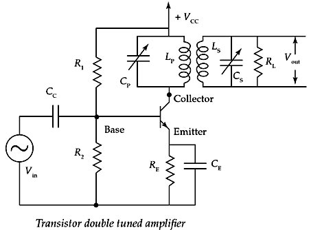
The double-tuned amplifier employs load impedance consisting of two circuits resonant at the same frequency and coupled together as shown in Fig. The frequency response of the double-tuned amplifier depends on the degree of coupling between the inductors in the two tank circuits. Here, the voltage developed across the tuned circuit is coupled inductively to another tuned circuit. Both tuned circuits are tuned to the same frequency.
Double-tuned Amplifiers are used mostly in Television, Radar, and other communication receivers. They provide constant amplification of signals over a selected passband and reject the signals sharply outside the passband.
As a common example, IF Transformers in radio receiver circuits contain Double-tuned circuits with stagger tuning to obtain the desired passband of 10 kHz. Tuning capacitances in the tuned circuits are of the order 50 to 120 pF. Q values range from 60 to 70. If a receiver contains single-stage IF Amplifier, there will be two IF Transformers. Whenever a radio receiver has two IF Amplifier stages for better selectivity, the IF Amplifier stages contain three IF Transformers. Each high-frequency transformer contains two tuned circuits, primary and secondary sides of the high-frequency transformer.
AM receivers use Intermediate Frequency (IF) of 455 kHz; FM receivers use 10.7 MHz.
The two tuned circuits in IF transformers are coupled by mutual inductance M with the coefficient of coupling M = K√LP.LS of coupling K depends upon the proximity of the two tuned circuits and in turn their inductors. The methods of coupling between the two coils modify the characteristics of the total double-tuned circuits and in turn the output frequency response of the Double-tuned Amplifier.
Ques.92. A transistor is a combination of two p-n junctions with their
P region connected together
N region connected together
N region connected to another P region
P region connected together and N region connected together✓
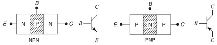
A Bipolar Junction Transistor (BJT) is a three-layer, two junction semiconductor device consisting of either two N-type and one P-type layer of material (NPN transistor) or two P-type and one N-type layer of material (PNP transistor). If a thin layer of N-type Silicon is sandwiched between two layers of P-type silicon. This transistor is referred to as PNP.
Alternatively, A NPN transistor is equivalent to two P-N junction diodes placed back to back with their very thin P-regions connected together. The necessary circuit diagram for the operation of NPN transistor is as shown in figure.
The term bipolar is to justify the fact that holes and electrons participate in the injection process into the oppositely polarised material. If only one carrier is employed (electron or hole). it is considered a unipolar device.
Ques.93. What are the ON/OFF terminals of a transistor when it is operated as a switch?
Collector to base
Collector to emitter✓
Base to collector
Emitter to base
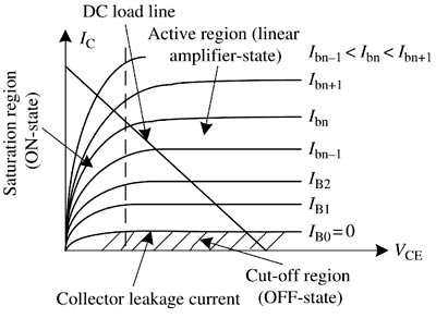
A transistor has three operating regions: cutoff (OFF), saturation (ON), and active. In power applications, a transistor works in the cutoff and saturation regions as a switch. In the cutoff region, the collector-emitter voltage, VCE, is equal to VC as there is no current going through it, so the transistor acts as an opened switch in this state. In the saturation region, the base current is sufficiently high that the collector-emitter voltage is very low; therefore, the transistor acts as a closed switch in this state. In the active region, the transistor works like an amplifier to adjust the collector-emitter voltage based on the base current.
From the characteristics of a transistor, it can be seen that the base current needs to be enough to have a transistor work as a switch. Thus, the ON or OFF state of a transistor is determined by the base current, and the collector and the emitter are considered as two terminals of a switch. The values of VC and RC determine the operating points of a transistor from the DC load line shown in Fig.
In the ON state, the collector-emitter voltage, VCE is near to zero, so the collector current should be equal to (VC − VCEsat) ⁄RC where VCEsat is the saturation voltage at which the voltage drop across the collector-emitter terminals of a transistor is the smallest. In other words, the collector-emitter voltage, VCE is saturated when the base current is equal to or greater than the saturation current, IB > IBsat; at this point, the collector current is maximal and the transistor has the smallest voltage drop across the collector-emitter terminals. In the OFF state, the collector current, lC is near to zero and the collector-emitter voltage, VCE is equal to the supply voltage, VC, which occurs when the base current IB = 0.
Ques.94. If negative feedback is used in the amplifier circuit, it
Increase distortion
Increase Gain
Reduce Distortion✓
No effect on distortion
Feedback is commonly used in amplifier circuits. A signal that is proportional to the output is compared with an input or a reference signal so that the desired output is obtained from the amplifier. The difference between the input and the feedback signals, called the error signal, is amplified by the amplifier. There are two types of feedback:
In negative feedback, the output signal (or a fraction of it) is continuously fed back to the input side and is subtracted from the input signal to create an error signal, which is then corrected by the amplifier to produce the desired output signal.
In positive feedback, the output signal (or a fraction of it) is continuously fed back to the input side and added to the input signal to create a larger error signal, which is then amplified to produce a larger output until the output reaches saturation voltage limit of the amplifier.
In negative feedback, the signal that is fed back to the input side is known as the feedback signal, and its polarity is opposite that of the input signal (i.e., it is out of phase by 180° with respect to the input signal). So the input voltage applied to the basic amplifier is decreased and correspondingly the output is decreased. Hence, the voltage gain is reduced. This type of feedback is known as negative or degenerative feedback.
The bandwidth with negative feedback increase by the factor (1 + Aβ) and gain decrease by the same factor.
Where A is the open-loop gain i.e gain without feedback
β is the feedback factor
The amount of feedback (1 + Aβ) is also called the de-sensitivity factor.
Negative feedback in an amplifier has four major benefits:
It stabilizes the overall gain of the amplifier with respect to parameter variations due to temperature, supply voltage, and so on
Noise Reduction: Negative feedback when used in amplifiers increases the signal to the noise ratio or causes the reduction in noise.
Increase in Input Impedance: Negative feedback increases the input impedance of amplifiers which is generally preferred in multistage amplifiers to reduce the loading effect.
Non-linear Distortion: Reduction Application of negative feedback to amplifiers causes the amplifier characteristics to be least non-linear or more linearized and the distortion gets reduced by a factor of 1/(1 + Aβ).
it increases the bandwidth.
There are two disadvantages of negative feedback:
The overall gain is reduced almost in direct proportion to the benefits, and it is often necessary to compensate for the decrease in gain by adding an extra amplifier stage
The circuit may tend to oscillate, in which case careful design is required to overcome this problem. Negative feedback is also known as degenerative feedback because it degenerates (or reduces the output signal.
Ques.95. The power factor of a synchronous motor, When the field is under-excited
Leading
Unity
Lagging✓
Zero
Unlike induction machines, synchronous machines can operate at lagging, leading and unity power factors. In an induction machine, the magnetizing current is required to establish flux in the air gap. This magnetizing current lags the voltage and therefore, the induction machine always operates at a lagging power factor.
On the other hand, in synchronous machine, the total air gap flux is produced by dc source and there is no use of lagging current from ac system for the production of air-gap flux. If dc excitation is decreased, lagging reactive power will be drawn from ac source to aid magnetization and thus machine will operate at lagging power factor. If dc excitation is more, the leading current is drawn from the ac source to compensate (oppose) the magnetization and the machine will operate a leading power factor.
Thus it can be concluded that an over-excited motor(Eb > V) draws leading current (acts like a capacitive load) but an under-excited motor(Eb < V) draws a lagging current (acts like an inductive load).
Ques.96. To limit the operating temperature of the synchronous motor, it should have proper
Current Rating✓
Voltage Rating
Power Factor
Speed
When a machine has to be designed and constructed, the choice of suitable materials and manufacturing technology becomes important. The following considerations are required which impose the limitations on the machine design:
Rated current:- Rated current is the maximum permissible current that can be maintained permanently, which at the same time does not cause any overheating, damages, faults, or accelerated aging. In AC machines, the rated current implies the RMS value of the winding current.
Electrical currents in windings of electrical machines produce losses and develop heat, increasing the temperature of conductors and insulation. Current in the windings creates Joule losses which are proportional to the square of the current. The temperature of the machine is increased in proportion to generated heat. If the current is increased beyond the rated current then the temperature of the synchronous motor will also increase.
This excessive temperature rise may cause insulation failure. The life of the machine depends upon the life of the insulation. If the machine is continuously operated above the specified temperature limit, the life of the insulation and hence the life of the machine will be reduced. By providing proper ventilation and
Saturation of the Magnetic Circuit: The saturation of the magnetic circuit disturbs the straight-line characteristics of magnetization (B-H) curve resulting in increased excitation required and hence higher cost for the field system.
Insulation: The insulating properties and the strength of the insulating materials are considered on account of breakdown due to excessive voltage gradients set up in the machine.
Mechanical Strength: The machine should have the ability to withstand centrifugal forces and other stresses.
Efficiency: The efficiency of the machine should be high for the low running cost. The specific magnetic and electric loading should be low to achieve high efficiency. With the low value of magnetic and electric loadings, the size of the machine will be larger and hence more capital cost (initial investment).
Ques.97. A synchronous machine with large air gap has
A higher value of stability limit
A higher synchronizing power
A small value of regulation
All options are correct✓
In Synchronous Machine the Magnetic Flux is set up separately by Field Winding. The Emf induced in the Stator Armature Winding is not by Mutual induction it is a Dynamically induced Emf due to relative motion between the Field and Conductors.
The length of the air gap greatly influences the performance of a synchronous machine. A large air gap offers a large reluctance to the path of flux produced by the armature MMF and thus reduces the effect of armature reaction. This results in a small value of synchronous reactance and a high value of SCR.
A high value of SCR (short circuit ratio) means that the synchronous reactance has a low value, synchronous machines with the low value of SCR thus have greater changes in voltage under fluctuations of load i.e., the inherent voltageregulation of the machine is poor.
Thus a machine with a large air gap has a high synchronizing power which makes the machine less sensitive to load variations.
Ques.98. Synchronous motor speed
Decreases as the load decreases
Increases as the load increases
Always remains constant✓
None of these
The principle of working of the synchronous motor is magnetic locking. Both stator and rotor and separately excited. The rotor catches the flux speed and gets locked with the revolving field of the stator and then rotates at that speed. In case of synchronous motor speed always remains constant equal to the synchronous speed, irrespective of load condition.
Ques.99. The magnitude of field flux in a 3-phase synchronous machine
Varies with speed
Remains constant at all loads✓
Varies with power factor
Varies with the load
In a synchronous motor, the counter Emf is proportional to the speed and field flux.
Since the speed is constant in a synchronous motor, therefore, field flux is substantially constant within the normal limit of operation.
If field excitation is increased thereby tending to increase the field flux that varies only slightly, there must be an automatic change in the armature MMF in order to offset the effect of the increased field excitation. The armature current must, therefore, contain a leading component, hence the leading current in a synchronous motor exerts a demagnetizing effect.
By the same reasoning, it follows that a weakening of the field excitation tends to draw a lagging current from the source of supply. For any set of operating conditions, there will be some value of field excitation which will cause the power factor to be unity, i.e., the current to be in phase with the terminal voltage.
When this condition exists while the motor is carrying its rated load, the motor is said to have normal excitation.
Ques.100. In a synchronous motor, the magnitude of back e.m.f depends on
The speed of the motor
DC excitation Only✓
Load on the motor
Both the speed and rotor flux
In case of the synchronous motor also, once the rotor starts rotating at synchronous speed, the stationary stator (armature) conductors cut the flux produced by the rotor. The only difference is conductors are stationary and flux is rotating. Due to this, there is an induced e.m.f. in the stator which according to Lenz’s law opposes the supply voltage. This induced e.m.f. is called back e.m f. It is denoted as Ebph i.e. back e.m.f. per phase. The back E.M.F is alternating in nature and its magnitude can be calculated by the equation.
Ebph = 4.44.φ.f.Tph
Where
ϕ is Flux per pole
Tph is the number of turns connected in series per phase
f be the frequency
As speed is always synchronous, the frequency is constant and hence magnitude of such back e.m.f. can be controlled by changing the flux φ produced by the rotor.
Ebph ∝ Φ
So back e.m.f. in case of the synchronous motor depends on the excitation given to the field winding and not on the speed, as speed is always constant.
For SSC JE 2018 SET-1 Electrical paper with complete solutionClick Here
For SSC JE 2018 SET-2 Electrical paper with complete solutionClick Here
For SSC JE 2018 SET-3 Electrical paper with complete solutionClick Here
For SSC JE 2018 SET-4 Electrical paper with complete solutionClick Here
For SSC JE 2018 SET-5 Electrical paper with complete solutionClick Here
For SSC JE 2017 Electrical paper with complete solutionClick Here
For SSC JE 2015 Electrical paper with complete solutionClick Here
For SSC JE 2014 (Evening shift) Electrical paper with complete solutionClick Here
For SSC JE 2014 (Morning shift) Electrical paper with complete solution Click Here
For SSC JE 2013 Electrical paper with complete solutionClick Here
For SSC JE 2012 Electrical paper with complete solutionClick Here
For SSC JE 2011 Electrical paper with complete solution Click Here
For SSC JE 2010 Electrical paper with complete solution Click Here
For SSC JE 2009 Electrical paper with complete solution Click Here