Ques.81. The incandescent lamp is filled by
- Argon Gas✓
- Oxygen Gas
- Carbon dioxide
- Sulfur oxide
An incandescent lamp is a glass bulb containing a filament joined to a metal base with copper lead-in wire (Figure). The filament is a tungsten wire that resists the flow of electricity. In doing so, the wire gets hot and glows, producing light. A lot of the energy used to create the heat that lights an incandescent bulb is waste, making, them less energy efficient than other types of lamps. Most incandescent lamps are filled with argon and nitrogen, which makes the use of a high filament temperature possible. The melting point of tungsten is 3,655K (6,170°F). Lamps filled with krypton gas have a longer life than argon and nitrogen lamps and cost more. Incandescent lamps Incandescent lamps have been around for a long time and are still commonly used, but they don’t perform as well as some of the other lamps on the market.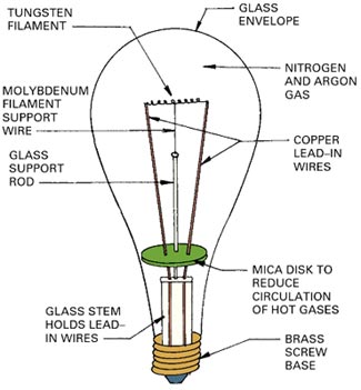
Ques.82. In house wiring which type of insulation is used?
- Rubber
- P.V.C✓
- V.I.R
- Paper
Insulating Materials:- The various insulating materials used in cables are as follows: Polyvinyl Chloride (PVC):- It is a synthetic compound material and comes as a white odorless, tasteless, chemically inert, non-inflammable, and insoluble powder. It is combined chemically with a plastic compound and is wed over the conductor as an insulation cover. PVC has a good dielectric strength and a dielectric constant of 5. Its maximum continuous temperature rating is 75° C. It is inert to oxygen and almost chemically stable, so it is preferred over VIR cable &. PVC insulated cables are usually employed for medium and low-voltage domestic, industrial lights, and power installations. Impregnated Paper:- This is used as an insulator in the case of power cables because it has low capacitance, high dielectric strength (30 kV/mm), and is economical. The paper is manufactured with wood pulp, rags, or plant fiber by a suitable chemical process. It has high resistance due to high resistivity under dry conditions. The drawback of this cable is that it absorbs a small amount of moisture only, which reduces the insulation resistance. Therefore, a paper insulated cable always requires some sort of protective covering and it is impregnated in insulating oil before use. Vulcanized India Rubber (VIR) it is useful for low-voltage power distribution systems only, because of its small size. It is prepared by mixing Indian rubber with mineral matter such as sulfur, zinc oxide, red lead, etc. It has a reasonable value of dielectric strength (15 kV/mm). Its use is limited because of its low melting point, low chemical resistance capability and short span of life. The advantage of using vulcanized India rubber is that when it is used for a cable, the cable becomes stronger and more durable. It can withstand high temperatures and remain more elastic than pure rubber. The drawback of using this material for insulation is that it attacks copper. Hence, before using VIR as insulation, the copper conductor must be tinned well. Silk and Cotton:– These types of insulation materials are used on conductors which are used for low voltage purposes. These insulated wires are usually used for instrument and motor winding.
Ques.83. The unit of solid angle is
- Solid angle
- Radian
- Steradian✓
- Candela
When the normal (perpendicular) lines are drawn from the boundary of a portion on the surface of a sphere, such that they meet at its center and form a cone, then the angle enclosed by the conical surface is called solid angle. Mathematically, the solid angle is the ratio of an area of the base of the conical surface (portion on the spherical surface of the sphere) to the square of the radius of the sphere. The unit of solid angle is the steradian Ω = 4πR2 ⁄ R2 = 4π (sr) Note:- The Radian is the SI unit for plane angles. Candela is the SI unit of luminous Intensity.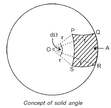
Ques.84. In case of frosted GLS lamps, the frosting of the shell is done by
- Acid etching✓
- Ammonia
- Ozone
- Salt-water
Ques.85. The resistance of the arc
- Decreases with an increase of the current✓
- Increases with an increase of the current
- Does not depend on current
- None of these
Arc Phenomenon When a short-circuit occurs, a heavy current flows through the contacts of the circuit breaker before they are opened by the protective system. At the instant when the contacts begin to separate, the contact area decreases rapidly and large fault current causes increased current density and hence rise in temperature. The heat produced in the medium between contacts (usually the medium is oil or air) is sufficient to ionize the air or vaporize and ionize the oil. The ionized air or vapor acts as the conductor and an arc is struck between the contacts. The p.d. between the contacts is quite small and is just sufficient to maintain the arc. The arc provides a low resistance path and consequently, the current in the circuit remains uninterrupted so long as the arc persists. During the arcing period, the current flowing between the contacts depends upon the arc resistance. The greater the arc resistance, the smaller the current that flows between the contacts. The arc resistance depends upon the following factors:
Ques.86. For welding duty the rectifier commonly used are
- Mercury arc rectifier
- Selenium metal rectifier✓
- Both Mercury arc rectifier and Selenium metal rectifier
- None of these
Arc welding is the widely used method of joining metal parts. Here the source of heat is an electric arc. Arc welding is a group of welding processes wherein the heating is produced with an electric arc or arcs, mostly without the application of pressure and with or without the use of fillet metal, depending upon the base plate thickness. DC arc welding machines: These are further divided as (i) DC generator set, motor-driven or engine driven and (ii) Transformer rectifier set. One big advantage of a DC welding set is that either straight or reverse polarity can be used. DC generator sets consist of a DC generator powered by either an AC electric motor or an engine (petrol or diesel). The generator set provides DC power in either straight polarity or reverses polarity using a polarity switch given on the machine. The generator supplies voltage usually between 15 and 45 volts across the arc and the open-circuit voltage is between 45 and 70 volts and the current supply is up to 600 amperes. DC Rectifier-type power sources also termed welding rectifiers are introduced in mid-1970s. They produce DC or, both AC and DC welding current. They are being utilized with either single-phase or three-phase input supply. They consist of a transformer and perform rectification of AC to DC using power semiconductor devices such as selenium rectifiers, silicon diodes or Silicon-Controlled Rectifiers (SCR).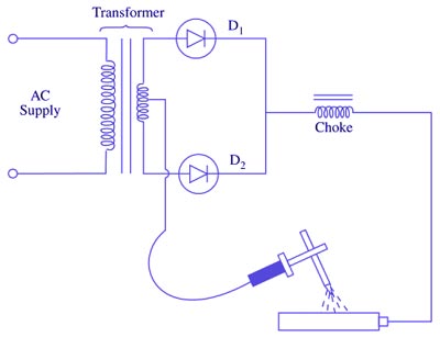
Ques.87. The device necessarily used for automatic temperature control in a furnace is
- Thermostat✓
- Auto-transformer
- Thermocouple
- All of the above
For the heat treatment process to be in control it is essential that the furnace is in control. If a furnace is out of control the heat treatment process is bound to be out of control. It’s like driving a car that is out of control; you don’t know whether or not you will reach your destination safely. An example of the need for critical temperature control is the solution heat treatment of titanium alloys which is performed at a temperature only slightly below (50 -150 °F). If the temperature is exceeded, tensile properties, especially ductility, are reduced and cannot be fully restored by subsequent heat treatment. The automatic controls used in an electric heating system are designed to ensure its safe and efficient operation. In a central heating system, the wall-mounted room thermostat is the control that governs the normal operation of the furnace. The operating principle is simple. The temperature selector on the thermostat is set for the desired temperature. When the temperature in the room falls below this setting, the thermostat will call for heat and cause the first heating circuit in the furnace to be turned on. There is generally a delay of about 15 seconds before the furnace blower starts. This prevents the blower from circulating cool air in the winter. After about 30 seconds, the second heating circuit is turned on. The other circuits are turned on one by one in the timed sequence. Note:- A thermocouple is a device used to measure the temperature, a thermostat is a control device that measures the temperature (could be using a thermocouple to do that) and comparing the measured temperature with the required temperature (setpoint) and based on these data control a heating and/or cooling device.
Ques.88. The ideal method of heating plastics is
- Coal/oil fired furnace
- Dielectric heating✓
- Induction heating
- Resistance heating
Dielectric heating, also known as electronic heating, RF (radio frequency) heating, and high-frequency heating, is the process in which a high-frequency alternating electric field, radio wave or microwave electromagnetic radiation heats a dielectric material. Dielectric heating (also called High-frequency capacitive heating) is employed for heating insulators like wood, plastics, and ceramics etc. A non-conducting material generates heat when subjected to an alternation electric field. This process wherein heating takes place due to dielectric loss is known as dielectric heating. The amount of heat produced depends on the value of the dielectric strength of the material. The non-conducting material acts as the job which is to be heated. This method is extensively used in plastic and wood industries. It is especially of immense utility where multiple woods are to be heated and glued. The heat supplied by this method is applied even] throughout the whole body. This method is also employed in the textile, rubber, chemical, and food industries. In this process, the job is placed in between two electrodes and the electrodes are fed with a very high-frequency supply. A capacitor is formed between the two electrodes and the job. The two electrodes act as the two plates of the capacitor and the job acts as to dielectric material between the two electrodes. The current flowing in the circuit is given by Ic = E/Xc Where Ic = Current flowing through the capacitor in Amp E = High-frequency supply voltage Xc = Capacitive reactance in Ohm During the charging and discharging of the capacitor, the molecular arrangement of the job changes because of the continuous stress created by the electric field. This change in molecular arrangement results in the generation of heat. When a solid dielectric material (Insulating) is subjected to an alternating electric field, it is not supposed to carry any current. However, in practice, some leakage current passes through it and power loss is takes place. This loss is called as the dielectric loss and result in the heating of the dielectric material.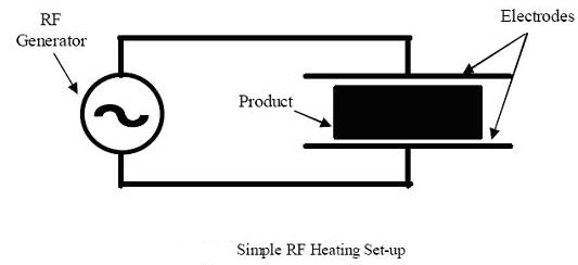
Ques.89. Which of the following element belongs to the same group of periodic tables as that of silicon and lead?
- Phosphorous
- Carbon✓
- Arsenic
- Mercury
Silicon is a member of Group 14 of the Periodic Table, the same group as carbon. Elements in this group have the unique property of being able to link to each other to form chains, a phenomenon is known as catenation or polymerization. Silicon in its elementary form has the same crystal structure as diamond. This is not too surprising, because in the periodic table silicon is a member; of the same group of elements as carbon.
Ques.90. The merging of a free electron and a hole is known as
- Recombination✓
- Extrusion
- Absorption
- Adsorption
Consider a semiconductor bar consists of a PN junction. Assume that the entire sample is a single crystal and the PN junction is just formed. The left half section of semiconductor bar is a P-type and the right half-section of semiconductor bar is N-type. The P-type region consists of majority carriers (holes) and negatively charged acceptor ions (negative ions). The N-type region contains majority carriers (electrons) and positively charged donor ions (positive ions). HOLE When energy is supplied to a semiconductor, a valence electron is lifted to a higher energy level, the departing electron leaves a vacancy in the valence band. This vacancy is called a hole. Thus, a vacancy left in the valence band because of the lifting of an electron from the valence band to conduction band is known as the hole. CREATION OF ELECTRON-HOLE PAIRS Whenever some external (heat) energy is supplied to a semiconductor, the valence electrons are projected up to the conduction band one after the other leaving behind a vacancy in the valence band called the hole. The number of electrons to be lifted from the valence band to the conduction band depends upon the quantity of external energy supplied to the semiconductor. If only one electron is lifted to the conduction band, then one hole is created in the valence band. Thus, each time an electron-hole pair is formed. RECOMBINATION OF ELECTRON-HOLE When some external energy is supplied to a semiconductor, the electrons of the valence band are lifted to the conduction band and become free leaving behind holes (vacancies) in the valence band. The conduction band orbits in which free electrons are moving are larger than valence band orbits in which holes are formed. Occasionally, the conduction-band orbit of one atom may intersect the whole orbit of another. Because of this generally, conduction-band electron falls into a hole. This merging of a free electron and a hole is called recombination. When recombination takes place, the hole does not move elsewhere, it just disappears. The recombination occurs continuously in a semiconductor. This would eventually fill every hole. However, incoming heat energy keeps producing new holes by lifting valence electrons up to the conduction band forming an electron-hole pair. This creation of electron-hole pair and their recombination goes on continuously. The average time between creation and the disappearance of an electron-hole pair is known as lifetime which varies from nanoseconds to several microseconds, depending upon various factors like crystal structure of the semiconductor etc.