
Ques 21. What is the ratio of no-load speed to full load speed of a 200 kVA, 12 poles, 2200 V, 3 phase, 60 Hz synchronous motor?
- Infinite
- 1
- 1.1
- 1.21
Explanation: Here Ns = 120 × f/p = 120 × 60/12 = 600 rpm Speed of the synchronous motor remains constant irrespective of the load of the motor ie speed at no load and full load remains 600 rpm hence ratio of speed from no load to full load will be 1.
Ques 22. In a synchronous motor if the back emf generated in the armature at no load is approximately equal to the applied voltage, then the
- The torque generated is maximum
- Motor is fully loaded
- Excitation is 100%
- No Excitation at all
Explanation: To find how the excitation affects the working of the synchronous motor, let us assume that it is an ideal machine having no armature winding resistance and no rotational losses. Let us also assume that the motor is connected to an infinite bus so that its terminal voltage and the supply frequency can be taken as constant. The ideal motor on no-load requires no armature current. This is possible only when the applied voltage is equal and opposite to the excitation emf. As the infinite bus frequency remains unchanged, the ideal motor runs at a constant speed and so the excitation emf can be changed only by changing the excitation (or field) current. When the excitation current is adjusted so as to make the excitation emf, Eb, equal to the applied voltage, V. the excitation is said to be normal or 100% excitation. Since no power is developed by the motor, the power angle, &, is zero. If the excitation current is increased above the normal value, the excitation emf, Eb, increases and becomes greater than the applied voltage, and the motor is said to be over-excited. In over-excited condition Eb > V If the excitation current is decreased below the normal value, the excitation emf, Eb, decreased and becomes less than the applied voltage, and the motor is said to be under-excited. In under excited condition Eb < VEffect of Change of Excitation on No-Load in Synchronous Motor
Ques 23. In a synchronous motor, the armature current has large values for
- High excitation
- Low excitation
- Both high and low excitation
- None of the above
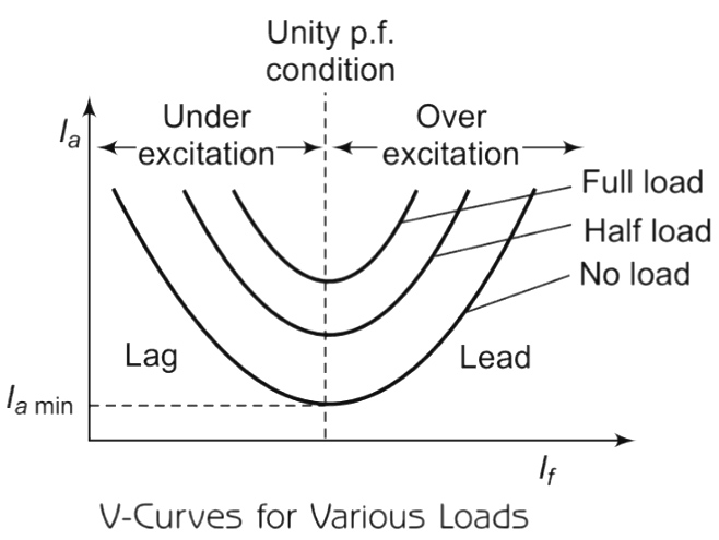
Explanation: The synchronous motor always adjusts its cosφ i.e., power factor nature so that Power component Ia cosφ remain constant when excitation of the motor is changed keeping the load constant. This is the reason why a synchronous motor reacts by changing its power factor to variable excitation conditions. Under excitation condition: When the excitation is adjusted in such a way that the magnitude of induced emf is less than the applied voltage (Eb < V) the excitation is called under excitation. Due to this, ER increases in magnitude. This means for constant Synchronous Impedance (Zs), the current drawn by the motor increases. But ER, the phase shift in such a way that, phasor Ia, also shifts (as ER ∧ Ia = θ) to keep the Power component of Ia i.e Ia cosφ components constant. So in under excited conditions, the current drawn by the motor increases. The power factor cosφ decreases and becomes more and more lagging in nature. Over excitation condition: The excitation to the field winding for which the induced emf becomes greater than the applied voltage (Eb > V) is called overexcitation. Due to the increased magnitude of Eb, ER also increases in magnitude. But the phase of ER also changes. Now (as ER ∧ Ia = θ) is constant, hence Ia also changes its phase, So φ changes. The Ia increases to keep Ia cosφ constant. The phase of ER changes so that Ia becomes leading with respect to Vph in over-excited conditions. So power factor of the motor becomes leading in nature. So overexcited synchronous motor works on leading power factor. So power factor decreases as over excitation increases but it becomes more and more leading in nature. Two important points stand out clearly from the above discussion : (i) The magnitude of armature current varies with excitation. The current has a large value both for low and high values of excitation (though it is lagging for low excitation and leading for higher excitation). In between, it has a minimum value corresponding to a certain excitation. T (ii) For the same input, armature current varies over a wide range and so causes the power factor also to vary accordingly. When over-excited, motor runs with leading p.f. and with lagging p.f. when under-excited. In between, the p.f. is unity. 
Ques 24. The construction of a synchronous motor resembles which of the following machine
- Differential compound motor
- Alternator
- Dc series motor
- Induction motor
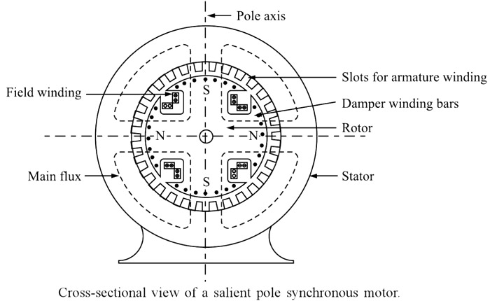
Explanation:Synchronous Motor Construction
Ques 25. The synchronous motors are not self-starting because
- The direction of torque on the rotor reverses after every half cycle.
- Slip is not present in synchronous machine
- Starting winding is not present in the synchronous machine
- DC excitation is used
Explanation: The synchronous motor works on the principle of magnetic locking. The operating principle can be explained with the help of a 2-Pole synchronous machine with the following steps. Let us consider a two-pole synchronous motor as shown in Figure. The three-phase supply is provided to the stator which induces two poles i.e North pole and the South pole on Stator. Since the supply in the stator is alternating in nature, therefore, its polarity changes in every half cycle, thus the poles of the stator also changes after every half cycle. The synchronous motor rotor is energized by the DC current. The field current (D.C Current) of the motor produces a steady-state magnetic field. Since the polarity of the D.C current is fixed therefore the poles of the rotor don’t vary. Therefore, there are two magnetic fields present in the machine. Stator poles changes in every half-cycle whereas rotor poles remain the same. Step 1. When a three-phase supply is given to the stator winding, a rotating magnetic field is produced in the stator. Step 2. Step-3.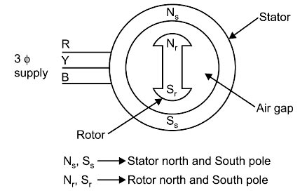

Ques 26. Due to which one of the following reasons a synchronous motor fails to pull into synchronism after applying D.C. field current?
- Low short circuit ratio
- High field current
- High core losses
- Low field current
Answer 4. Low field current Explanation:
Pull-in torque
Ques 27.When a synchronous motor is connected to an infinite bus, while. operating on leading power factor.
- Excitation voltage will be independent of the supply voltage.
- Excitation voltage will be more than the supply voltage.
- Excitation voltage will be less than the supply voltage.
- Excitation voltage will be equal to the supply voltage.
Explanation: The bus bars whose frequency and the phase magnitude of potential differences are not affected by changes in the condition of anyone machine connected to it are called infinite bus bars. or A network having zero impedance and infinite rotational inertia is also termed as Infinite bus-bars. An overexcited synchronous motor draws current at the leading power factor. If d.c. field excitation of a synchronous motor is such that the back emf Eb is greater than applied voltage V, then the motor is said to be over excited. An overexcited synchronous motor acts as a power factor correction device and is also known as a synchronous condenser. The variation of armature current and power factor as a function of field current is plotted to give a better insight. We can state that an over-excited synchronous motor draws a leading power factor current from the mains. The synchronous motor, therefore, when over-excited, in addition to driving some load, will work as a capacitor or condenser. A capacitor draws a leading power factor current. An over-excited synchronous motor draws the leading power factor current from the mains. An over-excited synchronous motor is also called a synchronous condenser. Synchronous motors are used as constant-speed drive motors. Over-excited synchronous motors are used to improve the power factor of electrical loads in industries. Generally, the motor is run on load, and by overexcitation, the system power factor is also improved.
Ques 28. Which of the following losses is not dissipated by the stator core surface in a synchronous motor?
- Eddy current losses in the conductors
- Iron losses in the stator
- Windage losses.
- Copper losses in the slot portion of the conductors
Explanation: The losses in synchronous machines are as follows: (a) Fixed losses:- Core loss, bearing, friction, and windage loss, brush friction loss. These losses are obtained from the no-load test. Core loss occurs because of the eddy currents and hysteresis caused by the main magnetic field. It is the difference between the power required to drive the synchronous machine with or without field excitation. This is taken at the rated voltage and speed. (b) I2R loss in armature winding, stray loss in iron and conductors:- Armature I2R loss is current2 × dc resistance R corrected at 70°C and not the effective resistance. This can be calculated when I and R are measured. Stray load losses are caused due to changes in the flux distribution due to load. This can be found by a short-circuit test. The short-circuit current is adjusted to the value of load current at which the loss is to be determined, then the stray load loss = mechanical power input friction and windage loss I2R loss. The synchronous machine is run at the rated speed. Ventilation loss is the power required to circulate cooling air in addition to the windage loss. (c) Excitation circuit losses:- These include field copper loss, rheostat loss. brush contact loss, exciter losses. Field copper loss = I2fRf, where If is the field current and Rf is the resistance of field winding. Rheostat loss is I2fRr, where Rr, is the resistance of the rheostat. Brush contact loss is taken as slip ring current. Exciter loss is considered when it is driven by a Synchronous machine and is part of the whole machine. Otherwise, it is changed to the plant and not to the alternator. Note:- If the machine is not excited (zero field current) and running on no-load, the core loss will be zero and only windage and friction loss takes place. If the machine is excited (field current is supplied), both windage and friction and core losses take place. Thus, the core loss can be computed by taking the difference of the power consumed by machines with excitation and without excitation. It is common practice to consider core loss under load and no-load conditions the same.Losses in Synchronous machine
Windage losses in the synchronous motor
Ques 29. The direction of rotation of the synchronous motor can be reversed by reversing
- Field winding
- The polarity of the rotor poles
- Supply phase sequence
- None of the above
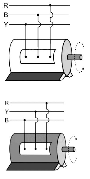
Explanation:Reversing a Synchronous Motor
Ques 30. In synchronous motor out of the following losses, which one will have the highest proportion?
- Stator copper losses
- Iron losses
- Eddy current losses
- Friction and windage losses
Explanation: A synchronous machine is used to convert mechanical energy into electrical energy or vice-versa. While doing so, the whole of input energy does not appear at the output but a part of it is lost in the form of heat in the surroundings. This wasted energy is called losses in the machine. These losses affect the efficiency of the machine. The various losses occurring in a synchronous machine can be sub-divided as 1. Copper losses: The various windings of the synchronous machine such as armature and field winding are made of copper and have some resistance. When current flows through them, there will be power loss proportional to the square of their respective currents. These power losses are called copper losses. In general, the various copper losses in a synchronous machine are: (i) Armature copper loss = I2R (ii) Field winding copper loss = I2fRf (iii) Brush contact loss = I2Rb The brush contact loss is generally included in the field winding copper losses. 2. Iron losses: The losses which occur in the iron parts of the DC machine are called iron losses or core losses or magnetic losses. Iron losses have a high proportion of losses occurring in the synchronous machine. Iron core losses in electrical induction machines operate with sinusoidal power supplies account for 15-25% of the total machine losses which are one of the major losses in electrical machines. These losses consist of the following: (i) Hysteresis loss: Whenever a magnetic material is subjected to reversal of magnetic flux, this loss occurs. It is due to the retentivity (a property) of the magnetic material. The Hysteresis losses are proportional to the frequency and the maximum flux density Bm in the air gap. (ii) Eddy current loss: When flux linking with the magnetic material changes (or flux is cut by the magnetic material) an emf is induced in it which circulates eddy currents through it. These eddy currents produce eddy current loss in the form of heat.The eddy current losses are proportional to the square of the electrical frequency. The electrical steel used in the stator and rotor of induction machines The major part of this loss occurs in the armature core. To minimize this loss, the armature core is laminated into thin sheets (0·3 to 0·5 mm) since this loss is directly proportional to the square of the thickness of the laminations. 3. Mechanical losses: As the field system of a synchronous machine is a rotating part, some power is required to overcome: (i) Air friction of rotating field system (windage loss). (ii) Friction at the bearing and friction between brushes and slip rings (friction loss). These losses are known as mechanical losses. To reduce these losses proper lubrication is done at the bearings. 4. Stray losses:- In addition to the iron losses, the core losses are also caused by the distortion of the magnetic field under load conditions and losses in the insulation of armature and field winding, these losses are called stray lasses. These losses are also included while determining the efficiency of synchronous machines.
The loss is basically due to the reversal of the magnetization of the armature core. It occurs in the armature (stator core). To minimize this loss, the armature core is made of silicon steel which has low hysteresis constant.
