Ques 21. Oil is provided in an oil-filled transformer for
- Lubrication
- Insulation
- cooling
- both cooling and insulation
Answer.4. both cooling and insulation Explanation: There are two main functions of the transformer oil Oil is an equally important part of a transformer’s overall insulation. (i) Electrical Insulation:- The main function of insulating oil in a transformer is to provide electrical insulation between the various energized parts; it also acts as a protective coating layer to prevent oxidation of the metal surfaces. (ii) Heat Dissipation/Coolant:- Another important function of the oil is to enhance heat dissipation. Transformer cores and windings get heated up during operation due to various power losses. Oil takes heat away from the core and windings by the process of conduction and carries heat to the surrounding tank, which is then radiated out to the atmosphere. In order that the mineral oil can dissipate the heat away effectively, certain specifications — including viscosity, pour point, and flash point — need to be maintained. (iii) Diagnostic Purposes:- The third (very useful) function of insulating oil in a transformer is that it acts as a health indicator for the device. Both the chemical and electrical conditions of the transformer can be monitored by examining the oil periodically. Oil samples are collected from designated sampling points of the tank and taken to laboratories for several tests to be performed. When a fault develops within the transformer, the energy is dissipated through the oil, which causes chemical degradation of the liquid. Testing oil samples for degradation products can provide useful information about the nature and severity of possible faults inside a transformer.Functions of Transformer Oil
Qus 22. Iron loss in a transformer can be determined by
- Open circuit test
- Short Circuit test
- Both 1 & 2
- None of the above
Answer.1. Open Circuit test Explanation: The purpose of the open-circuit test’ is to determine the excitation admittance of the transformer- equivalent circuit, the no-load loss, the no-load excitation current, and the no-load power factor.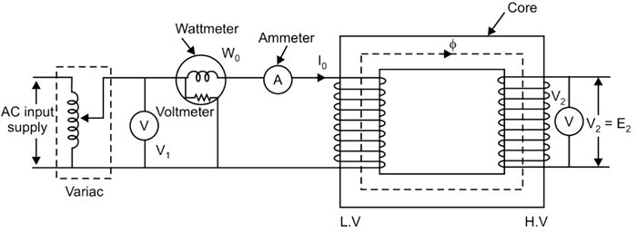
Ques 23. The path of magnetic flux in a transformer should have
- Low resistance
- Low reluctance
- High Resistance
- High Reluctance
2. Low reluctance Explanation: Also from the equation Flux = MMF/Re Where Re = Reluctance So lower the reluctance higher will be the flux flow
Qus 24. Buchholz relay is used for the protection
- Alternator
- AC motor
- DC motor
- Transformer
Answer.4. Transformer
Explanation
The Buchholz relay is a gas-operated relay used for the protection of oil-immersed transformers against all types of internal faults. The slow-developing faults called incipient faults in the transformer tank below oil level operate Buchholz relay which gives an alarm. If the faults are severe it disconnects the transformer from the supply.
It uses the principle that due to the faults, oil in the tank decomposes, generating the gases. The 70% component of such gases is hydrogen which is light and hence rises upwards towards the conservator through the pipe. The Buchholz relay is connected to the pipe, as shown in Fig. Due to the gas collected in the upper portion of the Buchholz relay, the relay operates and gives an alarm.
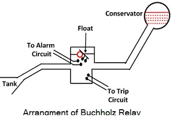
When gas gets accumulated in the upper part of the housing, the oil level inside the housing falls. Due to which the hollow float tilts and closes the contacts of the mercury switch attached to it. This completes the alarm circuit to sound an alarm. Due to this operator knows that there is some incipient fault in the transformer. The transformer is disconnected and the gas sample is tested. The alarm circuit does not immediately disconnect the transformer but gives the only indication to the operator. This is because sometimes bubbles in the oil circulating system may operate the alarm circuit though there is no fault.
However, if a serious fault such as an internal short circuit between phases, earth fault inside the tank etc. occurs then a considerable amount of gas gets generated. Thus due to fast reduce the level of oil, the pressure in the tank increases. This energizes the trip circuit which opens the circuit breaker. Thus transformer is totally disconnected from the supply.
The connecting pipe between the tank and the conservator should be as straight as possible and should slope upwards conservator at a small angle from the horizontal This angle should be between 10 to 11°
For the economic considerations, Buchholz relays are not provided for the transformers having a rating below 500 kVA.
Ques 25. The noise of the transformer is mainly due to
- Cooling fan
- magnetostriction in an iron core
- Mechanical vibration
- All of the above
Answer.2. Magnetostriction in iron core Explanation: The transformers using ferromagnetic core produces noise. Such a noise exists in the form of an electric hum around transformers. Such noise may be annoying to the nearby residential area. We can think of a transformer core, therefore, as behaving like a giant loudspeaker producing a continuous humming or buzzing noise, which is well within a human’s audible frequency range, and extremely irritating. The noise is produced due to the vibration of the enclosure and accessories. The vibrations are produced mainly due to stray magnetic fields and due to magnetostriction. Magnetostriction is a phenomenon due to which the length of the ferromagnetic core increases when magnetized and gets back to the original when demagnetized. Due to this, there is an increase and decrease in the cross-section of the core. As the laminations change their dimensions, the core vibrates to produce the noise. The core sound is dominant in no-load conditions. In load conditions, the vibrations in the tank and winding cause noise. The load noise is caused due to electromagnetic forces resulting from leakage fields produced by load currents. These forces are proportional to the square of the load currents. Similarly, there is noise due to sound generated by cooling equipment such as pumps and cooling fans. Thus the various factors responsible for producing transformer noise are, The noise productions in transformers can be reduced by The noise cannot be completely eliminated but taking the frequency of vibration of the transformer outside the audio frequency range is most helpful.
Noise in transformer
Ques 26. In a transformer the primary flux is _______ secondary flux.
- Greater than
- Smaller than
- Either 1 & 2
- Equal to
Answer.4. Equal to Explanation: To summarize, as current is drawn from the secondary, total flux momentarily decreases, and primary current increases restoring the flux lines to almost their original number. Thus, over the normal operating range of load § current, the total core flux does not change more than two or three percent.
Ques 27. What would happen if a transformer is connected to a DC supply?
- No effect
- Operate with high efficiency
- Damage the transformer
- Operate with low frequency
3.Damage the transformer Explanation:
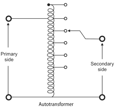
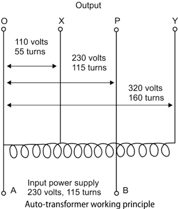
Qus 28. An autotransformer can be used as
- Step up device
- Step down device
- Both step up and step down
- None of the above
3. Both step up and step down Explanation: An autotransformer is a type of transformer that uses a single tapped winding rather than the two separate and electrically isolated windings used by mutual transformers. Because autotransformers don’t have separate windings, unlike mutual transformers there is no electrical isolation between the primary and secondary circuits.
Qus 29. The friction loss in a transformer is
- 20%
- 0%
- 50%
- more than 50%
2. 0% The transformer is a static device that is used to transfer electric power from one circuit to another without changing its frequency. The main function of a transformer is to raise as lower the voltage in a circuit with a corresponding decrease or increase in current at the same frequency. It works on the principle of Faraday’s law of Electromagnetic induction. Transformers have no moving parts, rugged and durable in construction. Since operation does not involve rotation of any armature, field system, or commutator, rotational, friction loss. and windage losses do not occur and its efficiency is thus high. For electrical ‘power’ purposes, i.e. transformers operating at 50 or 60 Hz, iron cores are essential and iron losses will occur. Winding copper losses are also present when current is supplied, nonetheless, the transformer is the most efficient of electrical machines and has a full-load efficiency of 95.5% for units of 5 kVA and 97.5% for units up to 1 MVA may be achieved.
Explanation:
Qus 30. In an Auto Transformer, The Primary and Secondary are_______Coupled
- Electrically only
- Magnetically only
- Both electrically & magnetically
- None of the above
3.Both electrically & magnetically Explanation: An autotransformer is a type of transformer that uses a single tapped winding rather than the two separate and electrically isolated windings used by mutual transformers. Because autotransformers don’t have separate windings, unlike mutual transformers there is no electrical isolation between the primary and secondary circuits. Where electrical isolation between the primary and secondary windings is unimportant, the use of an autotransformer has a number of advantages over a mutual transformer.