71. Which of the following is the definition of the proportional band of a controller?
The range of air output as measured variable varies from maximum to minimum
The range of measured variables from the set value
The range of measured variables through which the air output changes from minimum to maximum
None of the above
Answer.3. The range of measured variables through which the air output changes from minimum to maximum
Explanation:-
The proportional band is defined as the amount of change in input (or deviation), as a percent of span, required to cause the control output to change from 0% to 100% i.e minimum to maximum. Because a narrower proportional band gives greater output change for any given deviation, it therefore also makes the control performance more susceptible to oscillation. At the same time, a narrower proportional band reduces the offset.
Proportional Band ∝ 1/Gain
For example, suppose a controller for a heat exchange process has a scale range of 100 percent, corresponding to a temperature range of 100° F, if the proportional band adjustment of this controller is set at 5 percent, a temperature change of 5 % will produce 100 % change in the position of the steam valve (fully open or fully closed).
If the proportional band adjustment is set at 100 percent, a temperature change of 100% is required to produce the same change in the position of the valve. If the proportional band adjustment of this controller is 120 percent, a temperature of 120 % is required to produce a 100 percent change in the position of the valve.
72. In pneumatic control systems the control valve used as the final control element converts
Pressure signal to electric signal
Pressure signal to position change
Electric signal to pressure signal
Position change to the pressure signal
Answer.2. Pressure signal to position change
Explanation:-
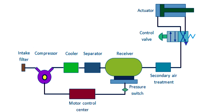
A pneumatic system is a system that uses compressed air to transmit and control energy. Pneumatic systems are used extensively in various industries. Most pneumatic systems rely on a constant supply of compressed air to make them work. This is provided by an air compressor. Pneumatic system control valve changes pressure signal to the position change.
Pneumatic control valves
This control valve functions according to an air pressure signal (0.2 to 1.0 kg/cm2G). The air signal can be applied directly to the valve actuator, but frequently a positioner is used to improve response and minimize hysteresis. Pneumatic control valves have been used for many years, and so have become relatively standardized and very reliable. They have many advantages, such as being relatively inexpensive, easy to maintain and equipped with essential features to prevent bursting.
73. which of the following instrument is used to measure pressure error?
Differential bellows and strain gauge
Strain gauge
Selsyn
Strain gauge and potentiometer
Answer.1. Differential bellows and strain gauge
Explanation:-
Methods of Pressure Measurement
Most pressure instruments measure a difference between two pressures one usually being that of the atmosphere. The different methods of pressure measurement are listed below:
Manometres:- The manometer is the simplest measuring instrument used for gauge pressure (low-range pressure) measurement, The action of all manometres depends on the effect of pressure exerted by a fluid at a depth.
Barometer:- Since manometres inherently measure the pressure difference between the two ends of the liquid column, if one end is at zero absolute pressure, then the difference in height of the liquid from the zero references indicates the absolute pressure. This is the principle of the barometer.
The C-Type Bourdon Tube Pressure Gauge:- The Bourdon tube is the most frequently used pressure gauge because of its simplicity and rugged construction. It covers range from 0.15 psig to 0100,000 psig, as well as vacuum from 0 to 30 inches of mercury.
Diaphragm Pressure Transducers:- Diaphragms are widely used for pressure (gauge pressure) and draft measurements, particularly in very low ranges. They can detect a pressure differential even in the range of 0 to 4 mm. The diaphragms can be in the form of flat corrugated or dished plates and the choice depends on the strength and amount of defection desired. In high precision instruments, the diaphragms are generally used in a pair, back to back, to form an elastic capsule.
Bellows:- The bellows-type gauges are used for the measurement of absolute pressures (normal as well as low pressure). It is somewhat more sensitive than Bourdon tube gauges. It is generally used for the range down to 155.1 mm Hg (3 psi). It may be used for even lower pressures up to 40mm Hg by making the bellows large enough. The bellows are made of an alloy that is ductile, has strength, and retinas its properties over long use, i.e., has very little hysteresis effect. They are used in two forms, in one arrangement, pressure is applied to one side of the bellows and the resulting deflection is counter balanced by a spring. This arrangement indicates the gauge pressure.
Pirani Gauge:- It consists of two wire filament the only filament serves as a reference and is sealed in an evacuated glass.
Electrical Pressure Transducers:-“A transducer is a device which converts one form of energy into another form of energy”. However, in the field of electrical instrumentation “, a transducer is defined as a device that converts a physical quantity, a physical condition, or mechanical output into a physical quantity, a physical condition or mechanical output into an electrical signal.
Strain Gauge Pressure Transducer:- Strain gauge is a passive type resistance pressure transducer whose electrical resistance changes when it is stretched or compressed. It can be attached to a pressure sensing diaphragm.
74. Which of the following devices is used for conversion of coordinates?
Microsyn
Selsyn
Synchro-resolver
Synchro-transformer
Answer.3. Synchro-resolver
Explanation:-
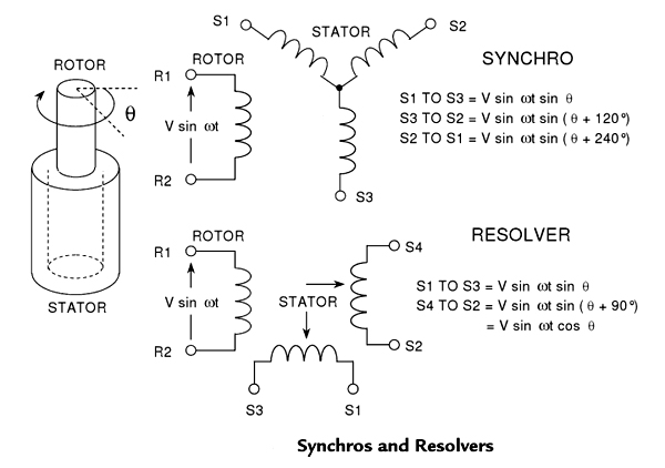
A Resolver is a form of synchro (Resolvers are very often called Synchro Resolvers) in which the windings on the stator and rotor are displaced mechanically at 90° to each other instead of 120° as in the case of synchros. Resolvers and synchros are transducers that convert the angular position and/or velocity of a rotating shaft to an electrical signal. The Resolver, therefore, exploits the sinusoidal relationship between the shaft angle and the output voltage. Synchro resolver is used for the conversion of coordinates.
A diagram of a typical synchro and resolver is shown in Figure. Both synchros and resolvers employ single-winding rotors that revolve inside fixed stators. In the case of a simple synchro, the stator has three windings oriented 120° apart and electrically connected in a Y-connection. Resolvers differ from synchros in that their stators have only two windings oriented at 90°.
In operation, synchros and resolvers resemble rotating transformers. The rotor winding is excited by an ac reference voltage, at frequencies up to a few kHz. The magnitude of the voltage induced in any stator winding is proportional to the sine of the angle,θ, between the rotor coil axis and the stator coil axis. In the case of a synchro, the voltage induced across any pair of stator terminals will be the vector sum of the voltages across the two connected coils.
75. The effect of error damping is to
Provide larger settling lime
Delay the response
Reduce steady-state error
None of the above
Answer.3. Reduce steady-state error
Explanation:-
Steady-State Error: For a step excitation, the difference between the desired output and the final value of any system is termed as the steady-state error of the system.
The function of damping is to reduce the amplitude and duration of the oscillation that may exist in the system. The simplest form of Damping is:-
Viscous Damping
Error rate Damping
Viscous Damping:- Viscous damping is the application of friction to the output load or shaft that is proportional to the output velocity. The amount of friction applied to the system is critical and will materially affect the results of the system. When just enough friction to prevent overshoot is applied, the system is said to be critically damped. When the friction is greater than that for critical damping, the system is overdamped. However, when damping is slightly less than critical, the system is said to be slightly underdamped, which is usually the desired condition. The application of friction absorbs power from the motor and is dissipated in the form of heat.
Error Rate Damping:-
Since no physical device can respond instantaneously to a sudden force, there is a time lag between the signal input of a servosystem and its output response.
Error-rate damping consists of introducing a voltage that is proportional to the rate of change of the error signal. This voltage is combined with the error signal in the proper ratio to obtain optimum servo operation with negligible over-shooting and oscillations.
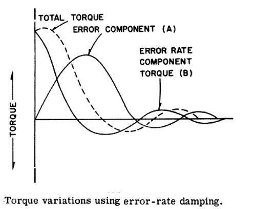
To overcome the disadvantages of the viscous dampers and still provide damping, error-rate damping is used. This type of damping consists of introducing a voltage that is proportional to the rate of change of the error signal. This voltage is fed to the servo-control amplifier and combined with the error signal. The figure shows the effect of error-rate damping on the torque output of the servomotor. Error damping is to reduce steady-state error as it is used to enhance the steady-state response of the system and this can be done by increasing the damping of the system.
Curve A shows the torque resulting from the error voltage.
curve B shows the torque resulting from the error-rate damper.
curve C depicts the resultant of curves A and B.
It should be noted that torque resulting from the damper increases the total torque as long as the error component is increasing. Once the error component starts to decrease, the error-rate damper produces a torque in an opposite direction reducing the transit time of the system.
The advantages of error-rate damping are:
Maximum damping occurs when a maximum rate of change of error signal is present. This normally would occur when the servo load reverses direction. Obviously, this is when maximum damping action is required.
Since a CHANGE in the signal causes damping, there is a minimum amount of damping when no signal, or a signal of constant strength, is present. This means a small steady-state error.
76. A phase lag lead network introduces in the output
Lag at all frequencies
Lag at high frequencies and lead at low frequencies
Lag at low frequencies and lead at high frequencies
None of the above
Answer.3. Lag at low frequencies and lead at high frequencies
Explanation:-
A lag lead compensator is a type of electrical network that generates phase lag as well as phase lead in the output signal at different frequencies when a steady-state sinusoidal input is provided to it. It is also known as lag lead network.
In the case of a lag lead compensator, the phase lead and phase lag occur at different frequency regions. Generally, at low-frequency phase lag characteristics are noticed in the output of the circuit. While at high frequency, we have phase lead characteristics.
Effects of Phase lag-lead compensator:- To get a fast response and good static accuracy, a lag-lead compensator is used. It also increases the low-frequency gain which improves the steady state. Since it increases the bandwidth of the system, the system response becomes very fast. In general, the phase lead portion of this compensator provides large bandwidth and hence shorter rise time and settling time, while the phase lag portion provides the major damping of the system.
77. Which of the following is the non-linearity caused by servomotor?
Static friction
Backlash
Saturation
None of the above
Answer.3. Saturation
Explanation:-
An ac servo motor is basically a two-phase induction motor. A two-phase servomotor differs from a normal induction motor as follows. The rotor of the servomotor is built with high resistance so that its X/R ratio is small and the torque-speed characteristic is nearly linear in contrast to the highly non-linear characteristic with a large X/R ratio.
For most servo systems driven by servo motors connected with mechanical components, there exist various non-smooth non-linearities including friction, saturation, dead-zone, etc., among which the input saturation is one of the most widely encountered phenomena due to the physical constraints on the maximum power of the driving motors. It is well-known that the presence of saturation may lead to sluggish transient responses, oscillations, and even instability. To manage the effect of input saturations, numerous research works have been carried out to design appropriate controllers for both linear or non-linear systems.
One limitation to predicting the stability of the servo system is that the theory applies only If the entire system is linear in operation. In Practice, the system is linear only over a limited range of operation end it becomes important to know the extent of this range In order that data be obtained for the system in linear operation.
A common source of nonlinearity occurs in the servo system And Is referred to as saturation. When a certain level of servo-system error voltage (voltage Input to the servo amplifier) is exceeded, one or more components exhibit saturation, and the output-input relation is no longer linear.
Although the error voltage can be measured directly when obtaining the frequency response of a closed-loop system, frequently it is easier to determine its limiting value by making a few sample calculations using the Input and output data.
Mechanical servo systems have been widely used in industrial robots, electronic processing, laser processing equipment, and manufacturing machines, etc. In such servo systems, the existence of non-smooth non-linear characteristics, such as friction, dead-zone, and hysteresis, may affect the tracking accuracy and even lead to instability.
Among these non-smooth non-linearities, friction can cause steady-state tracking errors, limit cycle oscillations, and even low-velocity crawlings. Therefore, it needs specific considerations to reduce or eliminate the effect of frictions in the control design.
78. ______can be extended to systems that are time-varying?
Bode-Nyquist stability methods
Transfer functions
Root locus design
State model representatives
Answer.4. State model representatives
Explanation:
Time-Varying Control System: If the parameters of a control system vary with time, such a control system is termed a time-varying control system. These do not depend on the nature of inputs and output, i.e., these may or may not be functions of time.
STATE MODEL VARIABLE REPRESENTATION OF LTI CONTROL SYSTEMS
The state variable approach, along with the output, yields information about the state of the system variable at some predetermined point along with the flow of signals. Its advantages are as follows:
It is a direct time-domain approach that provides a basis for modern control theory and system optimization.
It is a very powerful technique for the analysis and design of linear, non-linear, time-invariant, or time-varying multi-input, multi-output systems.
Easily amenable to solution through digital computers.
79. When the initial conditions of a system are specified to be zero it implies that the system is
At rest without any energy stored in it
Working normally with reference input
Working normally with zero reference input
At rest but stores energy
Answer.1. At rest without any energy stored in it
Explanation:-
INITIAL CONDITIONS
In Initial conditions, we find the change in selected variables in a circuit when one or more switches are moved from open to closed positions or vice versa.
⇒ t = 0 = indicates the time just before changing the position of the switch
⇒ t = 0 indicates the time when the position of the switch is changed
⇒ t = 0 indicates the time immediately after changing the position of the switch
A system is said to be relaxed if the system is causal, and at the initial time t0 the output of the system is zero, i.e., there is no stored energy in the system.
When all of the initial conditions of a system are equal to zero, the system is designated to be relaxed. However, in many practical applications, initial conditions, as well as the input sequence, must be considered to determine the output of a discrete-time system. A system is said to be relaxed at the time t0 if the energy stored at a time t0 is zero. This implies that the initial conditions of the model at t0 are zero.
80. Which of the following is the electromechanical device?
Induction relay
Thermocouple
LVDT
Any of the above
Answer.3. LVDT
Explanation:-
LINEAR VARIABLE DIFFERENTIAL TRANSFORMER (LVDT)
This is the most widely used inductive transducer for translating linear motion into an electrical signal. As we know that displacement is a vector quantity representing a change in position of a body or a point with respect to a reference. It can be linear or angular (rotational) motion. With the help of the displacement transducer, many other quantities, such as force, stress, pressure, velocity, and acceleration can be found. LVDT gives modulated output. The LVDT gives reasonably high output and hence requires less amplification.
The main electrical displacement transducers work on the principle of
Variable resistance: transducer is a strain gauge.
Variable inductance: transducer is a linear variable differential transformer
Variable capacitance: transducer is a parallel plate capacitor with a variable gap
Synchros and resolvers: used to measure angular displacement
Synchros are electromechanical devices that produce an output voltage depending on the angular position of the rotor and not on rotor speed, and it is different from a dc generator. The trade names for synchros are Selsyn, Antosyn, Telesyn. The four basic types of synchros are transmitters, receivers, transformers, and differentials.
81. A differentiator is usually not a part of a control system because it
Reduces damping
Reduces the gain margin
Increases input noise
Increases error
Answer.3. Increases input noise
Explanation:-
Differentiator acts as a high pass filter.
The disadvantage of using a differentiator is that for high frequency, capacitive impedance reduces and capacitor acts as short circuit, thus noise gets amplified.
82. If the gain of the critically damped system is increased it will behave as
Oscillatory
Critically undamped
Overdamped
Underdamped
Answer.4. Underdamped
Explanation:-
For a critically damped system, the value of the damping factor (ξ) is unity. Generally, a gain of the critically damped system is inversely proportional to the root of the damping factor ξ ∝ 1/√k.
Where k = system gain.
Therefore, if the gain of the system is doubled, the value of the damping factor will be less than unity and the system will exhibit under-damped.
83. In a control system integral error compensation _______ steady-state error
Increases
Minimizes
Does not have any effect on
Any of the above
Answer.2. Minimizes
Explanation:-
Integral Error Compensation
In Integral Error Compensation, the output response depends in some manner upon the integral of the actuating signal. This type of compensation is introduced by using a controller which produces an output signal consisting of two terms, one proportional to the actuating signal and the other proportional to its integral. This is known as the proportional plus integral controller (PI controller).
Characteristics of Integral Error Compensation
Steady-state error can be reduced by incorporating integral control.
The order of the system increases and higher-order systems are more likely to be unstable.
It is a low pass filter. Noise is filtered out.
84. Which of the following can be measured by LVDT?
Displacement
Velocity
Acceleration
Any of the above
Answer.4. Any of the above
Explanation:-
LINEAR VARIABLE DIFFERENTIAL TRANSFORMER (LVDT)
This is the most widely used inductive transducer for translating linear motion into an electrical signal. As we know that displacement is a vector quantity representing a change in position of a body or a point with respect to a reference. It can be linear or angular (rotational) motion. With the help of the displacement transducer, many other quantities, such as force, stress, pressure, velocity, and acceleration can be found. LVDT gives modulated output. The LVDT gives reasonably high output and hence requires less amplification.
The main electrical displacement transducers work on the principle of
Variable resistance: transducer is a strain gauge.
Variable inductance: transducer is a linear variable differential transformer
Variable capacitance: transducer is a parallel plate capacitor with a variable gap
Synchros and resolvers: used to measure angular displacement
85. The major disadvantage of a feedback system may be
Inaccuracy
Inefficiency
Unreliability
Instability
Answer.4. Instability
Explanation:-
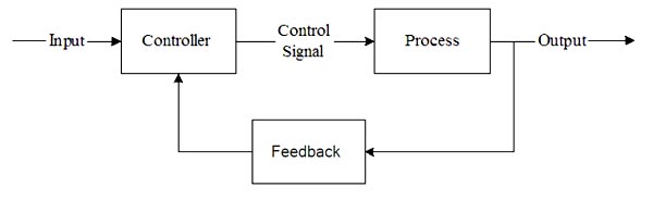
Feedback is that property of a closed-loop system that permits the output (or some other controlled variable) to be compared with the input to the system (or input to some other internally situated component or subsystem) so that the appropriate control action may be formed as some function of the output and input.
Feedback can be either negative or positive. In negative feedback, a portion of the output signal is subtracted from the input signal. In positive feedback, a portion of the output signal is added to the input signal.
Negative feedback, for example, tends to maintain a constant value of amplifier voltage gain against variations in transistor parameters, supply voltages, and temperature. Positive feedback is used in the design of oscillators and in a number of other applications.
Advantages of the Feedback System
Faster response to an input signal
Elective disturbance rejection
Better tracking of reference signals
Low sensitivity to system parameter errors (e.g., errors in plant or controller gains
Low sensitivity to changes in calibration errors Recalibration is unnecessary)
More accurate control of plant under disturbances and internal variations
Effective and flexible control tuning by varying the control gain.
Used to stabilize systems that are inherently unstable in the open-loop form
Disadvantages of Feedback Systems
Since feedback decreases the overall gain, this must be made up by an increase in the loop gain of the system, required additional hardware, and increased complexity.
The components m the feedback path must be made more accurate because feedback does not reduce the sensitivity to variations in these parameters. The result is a further increase in the overall cost.
The sensors required for the feedback path may introduce a small amount of noise in the system, therefore reducing the overall accuracy.
The power costs (due to high gains) are high
Sometimes obtaining the output measurement is either hard or not economically feasible.
Initial tuning is more difficult, especially if the bandwidth is narrow
There is always a steady-state error (with proportional controllers)
The introduction of feedback may lead to instability of the closed-loop system, even though me open-loop system may be stable. This is caused by inherent time lags in the system, With the result that what was intended as negative feedback may turn out to be positive feedback at some higher frequency. This was one of the first features of feedback observed when automatic control was introduced.
86. LVDT cannot measure
Weight
Pressure
Acceleration
Temperature
Answer.4. Temperature
Explanation:-
Linear variable differential transformer (LVDT) is one of the most popular variable inductance transducers used in many industrial applications like measurement of force, weight, pressure, and acceleration.
A thermocouple is used to measure the variation in the temperature.
87. None of the poles of the linear control system lie in the right half of the s-plane. For a bounded input, the output of this system
ls always bounded
Could be unbounded
Always tends to zero
None of the above
Answer.2. Could be unbounded
Explanation:-
For a linear control system with no poles in R.H.S of S-plane. But there may be a case of having repeated poles on jω axis which makes output unbounded.
88. Which one of the following methods is not used for the analysis of nonlinear control systems
Phase plane method
Describing function method
Liapunov’s method.
Piecewise linear method
Answer.4. Piecewise linear method
Explanation:-
Liapunov’s method is used for stability analysis of non-linear control systems. Piecewise linear method is also used for the general investigation of the non-linear system in addition to the Phase plane and describing function method.
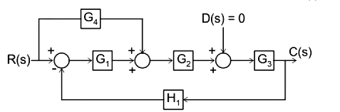
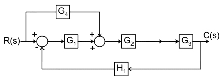
89. For the control system shown below, the transfer function C(s)/R(s) is