Ques.11. In which single-Phase motor, the rotor has no teeth or winding? (SSC-2018 Set-2)
- Split phase Motor
- Reluctance Motor
- Hysteresis Motor
- Universal Motor
Answer.3. Hysteresis Motor Explanation:- Teeth are usually stator or rotor laminated steel projections, usually with wire wrapped around the base of each projection. The purpose is to strengthen the magnetic field of the wire. Unfortunately, while this strengthens the available torque of the motor, it produces cogging. Cogging is the uneven torque produced between the stator permanent magnets and the rotor projections (teeth) due to the attraction of the magnets to the laminated steel of the projections on the rotor. Hysteresis motors are single-phase small size synchronous motors. The stator windings are similar to the stator windings of single-phase induction motors. In the auxiliary winding, a permanent value capacitor is connected. Like the main winding, the auxiliary winding is always connected to the supply. When the stator windings are connected to a single-phase supply a rotating field is produced which is rotating at synchronous speed. There is no winding provided on the rotor. The rotor is simply made of aluminum or other non-magnetic material having a ring of a special magnetic material such as cobalt or chromium mounted on it. The rotating field produced by the stator will induce eddy currents in the rotor. The rotor will get magnetized. But the magnetization of the rotor will lag the inducing revolving field by some angle due to the hysteresis effect. The rotating magnetic field will pull the rotor along with it and the rotor will rotate at synchronous speed. A constant torque will be developed upto the synchronous speed as shown in Fig. The performance of a single-phase hysteresis motor is silent (no noise) because there is no slot on the rotor and the rotor surface is smooth.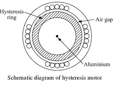

Ques.12. The range of efficiency for shaded pole Motors is (SSC-2018 Set-2)
- 95% to 99%
- 80% to 90%
- 50% to 75%
- 5% to 35%
Answer.4. 5% to 35% Explanation:- Shaded-pole motor has a salient pole staler similar to the stator of the dc machine. The pole is laminated to reduce the core losses. The pole is physically divided into two sections as shown in A heavy, short-circuited copper ring, called the shading coil, is placed on the smaller section of the pole. This section covers around one-third of the pole arc and is called the shaded portion of the pole. The remaining two-thirds section of the pole is referred to as the unshaded portion. The main single-phase winding is wound on the entire pole section. The rotor used is similar to the rotor of any other single-phase induction motor. When a single-phase supply is fed to the main winding, an alternating flux is produced in the pole. A portion of this flux links with the shading coil and induces a voltage in it. As shading coil is a short-circuited coil, a large current flows in it. The current in the shading band causes the flux in the shaded portion of the pole to lag the flux in the unshaded portion of the pole. Thus the flux in the shaded portion reaches its maximum value after the flux in the unshaded portion reaches its maximum. This is equivalent to a progressive shift of the flux from the unshaded to the shaded portion of the pole, that is it is similar to a rotating field moving from the unshaded to the shaded portion of the Pole. Hence. the motor reproduces a starting torque. Because of the small phase of displacement of the currents in the mail and the auxiliary winding and because of the winding misalignment lower than π/2 the start torque is very low. The shaded pole motor efficiency suffers greatly due to the presence of winding harmonic content, particularly the third harmonic which produces a dip in the speed-torque curve at approximately 1/3 synchronous speed. In addition, there are losses in the shading coils. These factors combine to make the shaded pole the least efficient and noisiest of the single-phase designs. It is used mostly in air moving applications where its low starting torque and the third harmonic dip can be tolerated. Some important Points of shaded Poles Motor Therefore shaded-pole motors are especially suited for small fans and pumps. Other applications are juice presses, clothe dryers, grills, clocks, simple butterfly control waves, massage apparatus, hot-air stoves, and cabinet fans. Drives for reversing duties can be built with two motors assembled homologously. Shaded-pole motors are low-cost motors. Because of their low efficiency, they mostly need intensive cooling.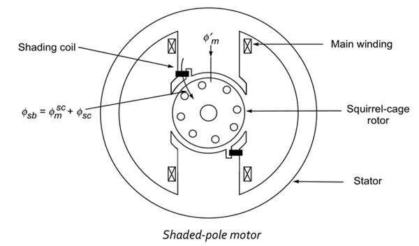
Ques.13. The direction of rotation of universal Motor can be reversed by reversing the flow of current through________ (SSC-2018 Set-2)
- Armature Winding
- Field Winding
- Either armature winding or field winding
- None of these
Answer.3. Either armature winding or field winding Explanation:- The direction of rotation of the universal motor can be changed in the same manner as changing the direction of rotation of a DC series motor. The direction of rotation of a salient pole type universal motor can be reversed by reversing the flow of current through either the armature or the field w iodine This can be easily done by interchanging the leads of the brush holders as shown in Fig.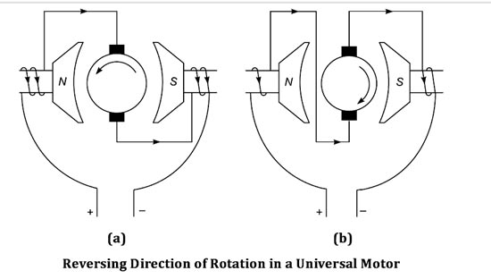
Ques.14. The wave of the armature m.m.f in DC machine is_____ (SSC-2018 Set-3)
- Square
- Rectangular
- Triangular
- Sinusoidal
Answer.3. Triangular Explanation:- The armature MMF of a distributed armature winding of a dc machine is triangular in shape as shown in Fig. In a D.C. machine, the armature M.M.F. wave has its maximum value at fixed points between the main poles, and its chief effect is to increase the flux density on one side of the pole and reduce it on the other At GNA (Geometrical neutral axis) MMF Attends it’s maximum value MMF and at MNA ( Magnetic neutral axis) MMF Attends zero value, it is alternating in nature. At MNA axis the armature conductors are situated in parallel with the field flux thus induced EMF is zero at that time and at GNA axis the armature conductors are situated at 90 ° with the field fluxes, between MNA and GNA the armature MMF slowly rise as the angle between an armature conductor and field flux increases the MMF induced on that conductor increases thus it creates a triangular form of armature MMF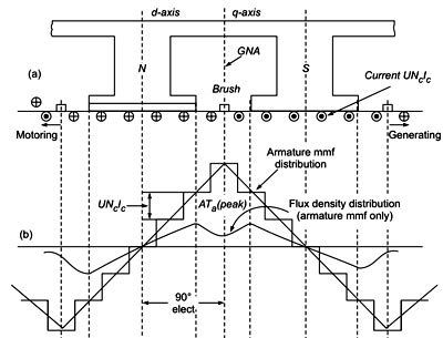
Ques.15. For a single-phase capacitor start Motor which of the following statements is valid? (SSC-2018 Set-3)
- The capacitor is used for power factor improvement
- The direction of rotation can be changed by reversing the main winding terminals
- The direction of rotation cannot be changed
- The direction of rotation can be changed by interchanging the supply terminals
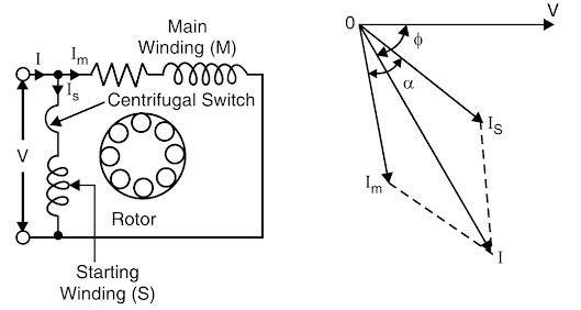
Answer.2. The direction of rotation can be changed by reversing the main winding terminals Explanation:- The capacitor-start motor is similar in construction to the split-phase motor. The capacitor-start motor has two stator windings: the start winding and the run winding. In addition, a capacitor and a normally closed contact operated by a centrifugal switch are connected in series with the start winding, as shown in Figure. As in the split-phase motor, the start winding is constructed of a few turns of fine-gauge wire, and the run winding is constructed of many turns of heavy gauge wire. The start winding has more resistance than does the run winding. The run winding has more reactance than does the start winding This creates a phase shift between the two winding this phase shift produces a rotating magnetic fie which causes the rotor to turn. The start capacitor used to produce a higher starting torque than to find in the split-phase motor. The turning rotor builds up speed. When a preset speed is reached, somewhere around 75% rated speed, the centrifugal switch contacts open, disconnecting the start winding and start capacitor from the circuit. The rotor continues to speed until the rated speed of the capacitor-start motor reached, operating with only the run winding connected to the power source. To reverse the direction of rotation of a capacitor-start motor, the connections to the start (auxiliary Winding ) or run (Main windings) are reversed (similar to that of split Phase Motor). Reversing the connections to both the start and run windings does not reverse the direction of rotation. As a rule, the connections to the start winding are the ones that are reversed.Capacitor-Start Motor

Ques.16. If a single-phase induction motor runs slower than normal, the most likely defect is (SSC-2018 Set-3)
- Worn Bearing
- Short-circuit in the winding
- Open-circuit in the winding
- None of these
Answer.1. Worn Bearing Explanation:- The factor that causes the slow speed of the motor is:- Note:- In the case of short-circuiting and open-circuit of induction motor the motor will not start.
Ques.17.The capacity of Single phase induction motor is limited by (SSC-2018 Set-3)
- Pulsating Torque
- Uniform Torque
- Non-Uniform Torque
- None of these
Answer.1. Pulsating Torque Explanation:- Consider the case that the rotor of the single-phase induction motor is stationary and the stator is connected to a single-phase supply. When a single-phase supply is connected to the stator winding a pulsating or Alternating magnetic field is produced. This pulsating field builds up in one direction, falls to zero and then builds up in the opposite direction. Under this condition, the resultant torque is zero and the pulsating magnetic field cannot produce rotation in the rotor. Therefore, a single-phase induction motor is not a self-starting motor. So if the rotor is ‘artificially’ started in one direction or the other, it will continue to rotate in that direction. This initial start is effected by adding a start winding, electrically a few degrees out-of-phase with the main stator winding. The field moves from the start winding to the main winding, and so the rotor receives a pulse start torque. The start winding is switched out of the circuit when the rotor is up to speed. The single-phase induction motor displays similar characteristics to those of the three-phase induction motor. The pulsating torque results from the interactions of the opposite fluxes and m.m.f.’s which cross each other at twice the synchronous speed such as the interaction of the forward flux with the backward rotor m.m.f. and of the backward flux with the forward rotor m.m.f. The interaction of the forward flux with the rotor forward m.m.f. and that of the backward flux with rotor backward m.m.f. produce constant torque. Note that the pulsating torque produces no average torque but rather produces a- humming effect and makes single-phase motors noisier than polyphase motors. Losses The alternation in field flux would cause excessive eddy current losses in the field core and yoke. The inductances of the field and armature windings cause abnormal voltage drops. So the torque developed is lower. Single-phase ac motors are employed for low-voltage, low-power applications -fractional-kW motors. They operate on the same basic principles as the 3-phase motor, but the pulsating single-phase field produces additional losses, reducing motor torque and the pulsating torque component increases the noise level of the motor. Therefore the capacity of the single-phase induction motor is limited by its pulsating torque hence the size of single-phase motors is limited to 5-hp.
Ques.18. Which of the following motor will give relatively high starting torque? (SSC-2018 Set-3)
- Capacitor end motor
- Capacitor start motor
- Split phase motor
- Split motor
Answer.2. Capacitor start motor Explanation:- The capacitor start motor is identical to the split-phase motor in both construction and operation, except that a capacitor is installed in series with the starting winding, as shown in Fig.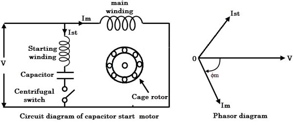
Ques.19. A centrifugal switch is provided for disconnecting the auxiliary winding in an (SSC-2018 Set-4)
- Capacitor start Motor
- Capacitor Run Motor
- Reluctance motor
- Hysteresis Motor
Answer.1. Capacitor start Motor Explanation:- The centrifugal switch is used to disconnect the start winding from the circuit when the motor reaches approximately 75% of the rated speed. A centrifugal switch is a mechanical device attached to the end of the shaft with weights that will sling outward when the motor reaches approximately 75% speed. For example, if the motor has a rated speed of 1725 rpm, the centrifugal weights will change position at 1294 r.p.m (1725 x 0.75) and open a switch to remove the start winding from the circuit. This switch is under a fairly large current load, so a spark will occur. If the switch fails to open its contacts and remove the start winding, the motor will draw too much current, and the overload device will cause it to stop. When the motor is de-energized, it will slow down and the centrifugal switch will close its contacts in preparation for the next motor starting attempt. The more the switch is used, the more its contacts will burn from the arc. If this type of motor is started many times, the first thing that will likely fail is the centrifugal switch. This switch makes an audible sound when the motor starts and stops. Hence if the starting switch fails to open when needed, the starting winding mill almost always overheats and burns out.
Ques.20. In a split-phase motor, the running winding should have (SSC-2018 Set-4)
- High resistance and low inductance
- Low resistance and high inductance
- High resistance as well as high inductance
- Low resistance as well as low inductance
Answer.2. Low resistance and high inductance Explanation:-