Ques.51. For a dc machine shunt resistance and armature resistance values are
High and High
High and Low✓
Low and Low
Low and High
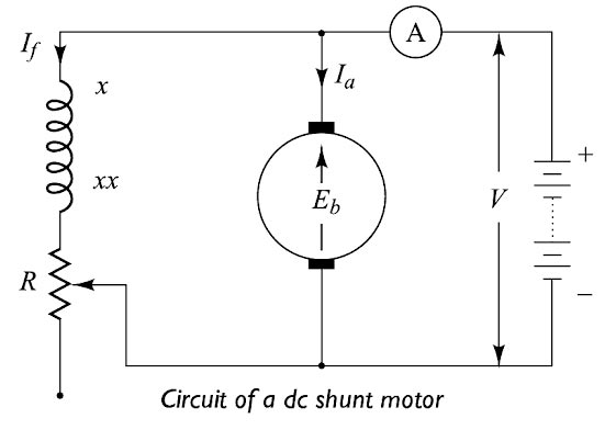
In DC machine the field resistance is low i.e the field resistance consists of less number of turns having a large cross-section area. While the resistance of the shunt is high i.e the more number of turns and smaller cross-section area.
The resistance of the shunt field winding is large so the current in the winding is small compared to the rated armature current of the machine. To produce the necessary m m.f.. the winding consists of many turns.
The resistance of the series field winding is made as low as possible so that voltage drop across the winding is minimum. To produce the same flux at rated conditions, the turns of a series winding are fewer than those of a shunt winding since the series winding carries the rated current of the machine.
Ques.52. If the field of a DC shunt motor gets opened while the motor is running, then the
Motor will become slow
The motor will attain the dangerously high speed✓
Armature current will drop
Armature will oscillate about original speed as the mean speed
If the field of a DC shunt motor gets opened while the motor is running, then the motor will attain the dangerously high speed,
In a dc machine, the field coils or field winding is excited by the current in order to produce the magnetic flux. In a DC shunt machine, the speed is Directly proportional to the back EMF and Inversely proportional to the flux.
N ∝ Eb/φ
Now if the field winding gets open then flux will become zero i.e φ = 0
∴ N ∝ Eb/0
or
N = ∞
Hence the speed of the DC Shunt Motor will attain the dangerous High Seed.
If the main field of a shunt motor or a compound motor is extremely weakened or if there is a complete loss of main field excitation, serious damage to the motor can occur under certain conditions of operation.
Since the speed of a dc motor is inversely proportional to flux, its speed tends to rise rapidly when the flux is decreased. If the field failure occurs on a motor that is coupled to a load, which can neither be removed nor be reduced to a very low value, the residual flux due to the open field will develop a torque that will not be able to sustain rotation. Thus the motor will stall, heavy current will be drawn from the mains and the overload relay will trip.
On the other hand if field failure on an unloaded motor or if the application is such that it permits the motor to be unloaded or overhauled as in the ease of a hoist, the motor will not stall but instead its armature will accelerate quickly to a mechanically dangerous high speed or there will be destructive commutation. To prevent the above situation of overspeeding, a field failure relay is used.
Ques.53. Inter Poles winding is connected in
Series with the armature✓
Series with the main pole
Parallel with the Armature
Parallel with the main Poles
Interpoles In DC Machine
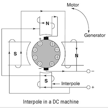
In DC machine One way to reduce the effects of armature reaction is to place small auxiliary poles called “interpoles” between the main field poles. The interpoles have a few turns of large wire and are connected in series with the armature.
One of the disadvantages of armature reaction is brush shifting, therefore a person is always required to adjust the brush position in the machine at every load change. We observe that sparking in the brushes can be avoided if the voltage in the coils undergoing commutation is made zero.
This method tries to do just the same. Small poles called commutating poles or interpoles are introduced in between the main poles along the geometrical neutral axis. Brushes are also set on this axis and kept fixed at this position for all the loads. The interpole winding has fewer turns of heavy copper conductors.
Interpoles are connected in series with the armature winding so that they carry full armature current, as shown in Fig. As the load on the machine is increased, the current passing through the interpoles also increases, hence the flux produced by the interpoles is very large. Consequently, the large voltage is induced in the conductor that opposes the voltage due to the neutral plane shift and the net result is that they neutralize each other.
Note that the interpoles can be used equally effectively in motors as well as in generators. When the mode of operation of the machine changes from the motor to the generator, the currents in the armature and the interpoles is reverses in direction. Therefore, their voltage effects cancel each other out.
Thus, we can conclude that:
In a generator, interpoles must have the same polarity as the next upcoming pole.
In a motor, interpoles must have the same polarity as the previous main pole.
The mmf induced on the interpoles must be sufficient enough to neutralize the effect of armature reaction and to produce enough field in the interpole winding to overcome the reactance voltage due to commutation.
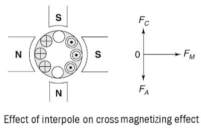
Another important function of the interpole is to neutralize the cross-magnetizing effect of the armature reaction, as shown in Fig. Here, vector FM represents the mmf due to the main poles, FA represents the cross-magnetizing mmf due to the armature reaction and FC represents the interpole mmf which is directly opposite to the FA so that they cancel each other out.
It is important to note here that the interpoles do not affect the flux distribution under the pole faces. So, even by using the interpoles in the machine, the flux weakening problem is not completely eliminated. Most medium-sized general-purpose motors correct the sparking problems with the interpoles and just live with the flux weakening problems.
Main Functions of the Interpole
The interpole neutralizes the reactance voltage and gives a spark-free commutation.
It neutralizes the cross-magnetizing effect of armature reaction so that the brushes are not required to be shifted from its original position for any load.
Ques.54. In the large machine, the flat copper strips known as
Windings
Bushes
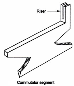
Risers✓
Either of these
In large machines, flat copper strips known as risers are used forming clip connections to armature bar conductors as shown in Figure.
Ques.55. Lap winding is preferred for
Low current and Low Voltage
High current and High Voltage
High current and Low Voltage✓
Low current and High Voltage
Armature Winding
An armature is that part of the DC machine where EMF is induced.
Armature coils are wound on the armature core and placed inside the armature slots.
Two methods can be used to wound armature coil:
Lap winding
Wave Winding
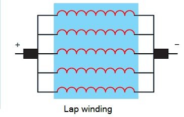
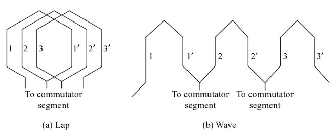
Lap winding: Here, the end of one coil is connected to the beginning of the next coil. If connections are made this way the coils look as if they are superimposed on each other and then given a push in one direction as shown in Fig.
Lap wound armatures are constructed with relatively few turns of large wire. They are commonly used in machines that are intended to operate on low voltage and high currents, such as starter motors in automobiles, streetcars, and trolleys. Lap wound armatures have their windings connected in parallel with each other.
Wave winding is another type of armature winding. In this winding, the end of one coil is connected to the starting of another coil of the same polarity as that of the first coil.
Wave wound armatures are intended for used in high voltage, low current machines, such as high voltage generators. The armature windings are connected in series . in a generator, the voltage produced in each winding combines, to increase the total output voltage. In a motor, the voltage applied to the circuit is divided across each winding.
Ques.56. Scott connections are used for
Single-phase to three-phase transformation
Three Phase to Single Phase transformation
Three-phase to two-phase transformation✓
Any of the above
SCOTT CONNECTION
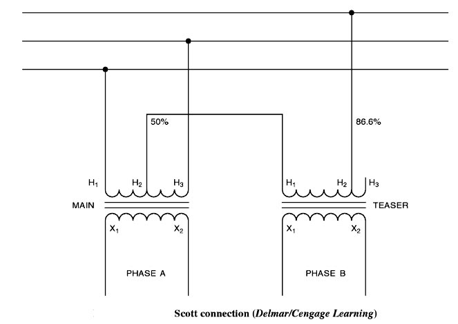
The Scott connection is used to convert three-phase power into two-phase power into two single-phase transformers. The Scott connection is very similar to the T connection that one transformer, called the main transformer, must have a center or 50% tap, and t second or teaser transformer must have an 86.6% tap on the primary side. The difference between the Scott and T connections lies in the connection of the secondary winding (Figure). In the Scott connection, the secondary windings of each transformer provide the phases of a two-phase system. The voltages of the secondary windings are 90° out of phase with each other. The Scott connection is generally used to provide two-phase power for the operation of two-phase motors.
Ques.57. The primary and secondary windings of an Auto-transformer are
Magnetically coupled
Electrically coupled
Both magnetically and electrically coupled✓
None of these
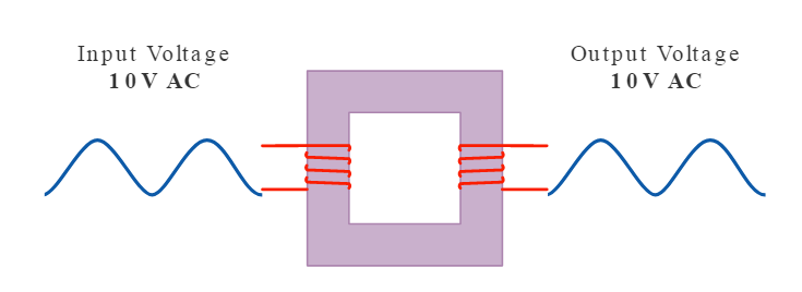
In the conventional two-winding transformer the primary winding is electrically insulated from the secondary winding. The two windings are coupled together magnetically by a common core. Thus, it is a magnetic induction that is responsible for the energy transfer from the primary to the secondary winding.
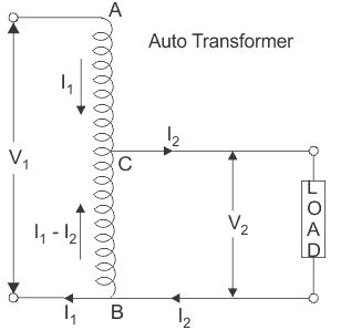
When the two windings of a transformer are also interconnected electrically, it is called an autotransformer. An autotransformer may have a single continuous winding serving as both primary and secondary winding, or it can consist of two or more distinct coils wound on the same magnetic core. In either case, the principle of operation is the same. The direct electrical connection between the windings ensures that a part of the energy is transferred from the primary to the secondary winding by conduction. The magnetic coupling between the windings guarantees that some of the energy is also delivered by induction.
Ques.58. A 40KVA transformer has a core loss of 450 W and a total loss of 800 W. Find the copper loss for Maximum efficiency.
350 W
800 W
450 W✓
300 W
It means that the efficiency is maximum at a load when the copper loss (variable loss) equals the core loss (constant loss). Thus for maximum efficiency
Ques.59. The difference between the stator synchronous speed and rotor speed is called
Leading speed
Lagging speed
Slip Speed✓
Slow Speed
The Slip Speed is defined as the difference between the stator synchronous speed and Rotor speed of an induction motor.
Slip speed = Ns − Nr
Ques.60. In three-phase induction motor maximum torque is Inversely Proportional to the
Stator Voltage
Speed of Rotor
Rotor Reactance✓
Decreasing Slip speed
The torque of rotor under running condition is
$\begin{array}{l}T = \dfrac{{K{\rm{ s}}{E_2}^2{\rm{ }}{R_2}}}{{{R_2}^2 + {{\left( {s{X_2}} \right)}^2}}}\\\\{\text{Slip Corresponding to Max torque}}\\\\s = \dfrac{{{R_2}}}{{{X_2}}}\\\\{\text{Putting the value of slip in above equation we get}}\\\\T = \dfrac{{K{\rm{ }}{R_2}/{X_2}{E_2}^2{\rm{ }}}}{{{R_2}^2 + \left( {{R_2}^2/{X_2}^2} \right).{X_2}^2}} = K\dfrac{{{E_2}^2}}{{2{X_2}}}\end{array}$
Hence it can be concluded that the maximum torque 3 phase induction motor is inversely proportional to the rotor reactance.
The maximum torque is not dependent on the rotor resistance R2. But the slip at which it occurs i.e. the speed at which it occurs depends on the value of rotor resistance R2.