Ques 21. Which one of the following is the S.I unit of the magnetic field strength?
Weber
Tesla
Ampere-Meter
Ampere/Meter✓
MAGNETIC FIELD INTENSITY
Magnetic field Intensity (H) is also called Magnetic field Strength, Magnetic Intensity, Magnetic field, Magnetic Force and Magnetization Force.
Magnetic Field Strength (H) gives the quantitative measure of the strongness or weakness of the magnetic field.
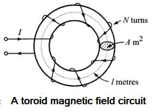
Suppose that a current of I amperes flows through a coil of N turns wound on a toroid of length I meters. The MMF is the total current linked to the magnetic circuit i.e IN ampere-turns. If the magnetic circuit is homogeneous and of a uniform cross-sectional area, the MMF per meter length of the magnetic circuit is termed the magneticfield strength, magnetic field intensity, or magnetizing force. It is represented by the symbol H and is measured in ampere-turns per meter (At/m).
$H = \dfrac{{NI}}{l}{\text{ AT/m}}$
Hence the magnetic field Intensity can be defined as the ratio of applied MMF to the length of the path that it acts over.
Note:- Magnetic field intensity, H, is independent of the medium. Its value depends only on the number of turns N and the current I flowing in the coil.
Magnetic Field Strength is equivalent to the Voltage gradient in an Electrical Circuit.
Ques.22. What is the bandwidth (in kHz) of a series RLC circuit having the resistance, inductance, and capacitance of 80 Ohms, 2 mH, and 0.01 mF respectively?
The bandwidth of the series RLC circuit is given as
B.W = R/L
B.W = 80 ⁄ (2 × 10⁻³)
B.W = 40 Hz
Ques.23. A 3-phase star connected system is supplied by a line voltage of 440 V. The value of the current is 50 A. What is the power (in kW) consumed by the system, if the current lags the voltage by 45 degrees?
8.95
24
26.94✓
47
Given
Line voltage VL = 440 V
Phase current Iph = 50 A
Phase angle φ = 45°
In star connection the line current and phase current are equal i.e Iph = IL = 50A
The power in 3-phase star connection is given as
P = √3 × VL × IL × cos45°
= √3 × 440 × 50 × cos45°
P = 26940.3 watt
Power = 26.94 kW
Ques.24. If the magnetic susceptibility of any material is less than zero then the material is
Paramagnetic
Ferromagnetic
Diamagnetic✓
Ferrimagnetic
The magnetic susceptibility expresses the responsiveness of a material to the applied magnetic field and can vary with the external applied magnetic field.
The symbol for magnetic susceptibility is χ and a magnetic susceptibility is a number with no units.
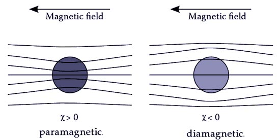
Materials with positive susceptibility have a field-induced within them that results in a total field that is greater than the strength of the magnetic field in which they are placed. Such materials are described as paramagnetic.
Materials with negative susceptibility have an induced field that opposes the field in which the material has been placed, so the talc field within the material is lower than the field in which they are placed. Such materials are described as diamagnetic.
For materials with positive susceptibility, the material is pushed toward stronger magnetic fields as it tends to lower potential energy whereas an opposite response for materials with negative susceptibility. Hence, materials with negative susceptibility (diamagnetic materials) are repelled and pushed toward weaker magnetic fields and materials with positive susceptibility (paramagnetic, ferromagnetic, ferromagnetic, and antiferromagnetic) are pulled toward stronger magnetic fields.
Ques.25. Determine the reluctance (in Amp-turns/Wb) of a coil, when the flux through the coil is 15 Wb and the produced MMF is 30 Amp-turns.
4
2✓
1
3
Similar to the resistance characteristic in electricity, we have reluctance in magnetism which is the property of the substance that opposes the magnetic flux through it.
The reluctance of any part of a magnetic circuit may be defined as the ratio of the drop in magnetomotive force to the flux produced in that part of the circuit. It is measured in ampere-turns/Weber and is denoted by S.
Reluctance = m.m.f ⁄ flux
Reluctance = 30 ⁄ 15
Reluctance = 2 Amp-turns/Wb
Ques.26. Determine the value of produced mmf (in Amp-turns) in a coil if the coil has a 120 turns carrying a current of 0.1 A.
12✓
14
16
18
Magnetomotive force (mmf): It is defined as the force that drives magnetic flux throng the magnetic circuit. In all practical magnetic circuits, this is provided using a current-carrying winding (coil), and is the product of the current and the number of turns in the winding. Its SI unit of measurement is the ampere.
m.m.fFm = N.I Ampere-turn
where N is the number of conductors (or turns) and I is the current in amperes. The unit of mmf is sometimes expressed as ‘ampere-turns’. However, since ‘turns’ have no dimensions, the Sl unit of mmf is the amp.
Given
Number of turns N = 120 turns
Current I = 0.1
Fm = 120 × 0.1
Fm = 12
Ques.27. What is the magnitude of the reactive power (in kVAR) of a balanced 3-phase delta connected system having a line voltage of 400 V and a line current of 50 A and the phase difference between the voltage and current is 53.13 degrees?
0.2771
2.771
27.71✓
277.1
Given
Line Voltage VL = 400 V
Line current IL = 50A
Phase angle φ = 53.13
The reactive power of three-phase AC circuit is given as
Q = √3 × VL × IL × sinφ
Q = √3 × 400 × 50 × sin 53.13°
Q = √3 × 400 × 50 × 0.8
Q = 27712.8 VAR
or
Q = 27.71 KVAR
Ques.28. Determine the magnitude of EMF (in V) induced between the axis of rotation and the rim of the disc, when the disc of radius 10 cm rotates with an angular velocity of 60 revolutions per second and is placed in the magnetic field of 3 T acting parallel to the rotation of the disc.
Ques.29. What will be the value of current (in A) in a 50 cm long air-core solenoid, if the value of the magnetic field at the center of the solenoid is 5 mT and the solenoid has 300 turns?
6.63✓
5.63
4.36
8.25
The magnetic flux density at the center of an air core solenoid is given as
Ques.30. Determine the maximum flux density (in T) of a material having an eddy current coefficient of 2, a thickness of 4 mm, and a volume of 20 cu meter, which is supplied by the frequency of 50 Hz when the material has eddy current loss of 6 W.
2.24
3.34
1.94✓
1.21
Eddy current losses in the transformer is given by
Eddy current losses = Ke × Bm2 × f2 × V ×t2
Where Ke = Eddy current constant = 2 t = thickness of the core = 4 mm = 4 × 10⁻³ V = Volume of material = 20m3 Bm =Maximum flux density = ? f = frequency = 50 Hz Eddy current losses = 6W