Ques.71. The output Resistance (in kΩ) of the common base transistor is of the order of
- 1
- 50
- 100✓
- None of these
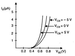
In this circuit configuration of a transistor, the base terminal is used as a common terminal between input and output as depicted in Fig. The input signal is applied between the emitter and base terminals. The output will be taken from the collector and base terminals. To explain the operation of NPN and PNP transistors, the common base configuration is used. Characteristic of common base (CB) There are two important characteristics of CE (1) input characteristics. (2) Output characteristics. Input Characteristic. It is the curve between base current IB and emitter-base voltage VBE at constant collector-base voltage VCB. The emitter current IE increases rapidly with a small increase in emitter-baa voltage VEB it means that input resistance is very small. In fact, the input resistance is the opposition offered to the signal current. As a very small VEB is sufficient to produce a large flow of emitter current, therefore, the input resistance is quite small, of the order of a few ohms. Output Characteristic. It is the curve between collector current Ic and collector-base voltage VCB at constant emitter current IE. A very large change in collector-base voltage produces only a tiny change in collector current. This means that output resistance is very high in the order of 100 KΩ.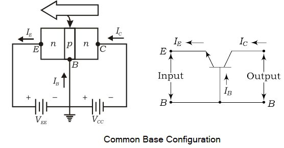
Ques.72. For Proper Operation of the transistor, its collector should have
- Proper Forward Bias
- Proper Reverse Bias✓
- Very small size
- None of these
A Bipolar Junction Transistor (BJT) is a three-layer, two junction semiconductor device consisting of either two N-type and one P-type layer of material (NPN transistor) or two P-type and one N-type layer of material (PNP transistor). A transistor can be visualized as two back-to-back connected diodes; by placing two PN junctions together, we can create a bipolar transistor with the three terminals – emitter, base, and collector. The term bipolar is to justify the fact that holes and electrons participate in the injection process into the oppositely polarised material. If only one carrier is employed (electron or hole), it is considered a unipolar device. For proper working of the transistor, the two junctions of the transistor should be properly biased, the base-emitter (J1) junction should be forward biased and the base-collector (J2) junction should be reverse biased. In a PNP transistor, the majority of charge carriers are holes, and germanium is favored for these devices. In an NPN transistor, the majority of charge carriers are electrons and silicon is best for NPN transistors. The thin and lightly doped middle layer is known as the base (B) and the two outer regions are known as the emitter (E) and the collector (C). Under the proper operating conditions, the emitter region emits or injects the majority of charge carriers into the base region and because the base is very thin, most of these electrons will ultimately reach the collector. The emitter is highly doped to reduce resistance and emit more majority charge carriers. The collector is lightly doped to reduce the junction capacitance of the collector-base junction. The schematics and the circuit symbols for bipolar transistors are shown in Fig. The arrows on the schematic symbols indicate the direction of emitter-current flow. The collector is usually at a higher voltage than the emitter and for proper operation, the base-emitter junction is forward biased while the collector-base junction is reverse biased.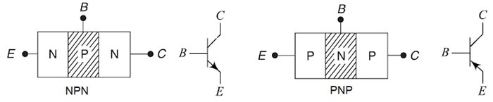
Ques.73. What is the characteristics of the common collector configuration amplifier with respect to the input and output impedance?
- Low Input Impedance and High Output Impedance
- High input Impedance and Low Output Impedance✓
- Low Input Impedance and Low Output Impedance
- High input Impedance and High Output Impedance
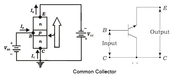
In a common-collector configuration, the collector terminal of a transistor is connected as a common terminal between input and output as shown in fig. The base and collector terminals are used to apply the input signal whereas the output signal is obtained. The CC configuration is also commonly known as the emitter follower or the voltage follower. This is because the output signal across the emitter is almost the replica of the input signal with little loss. In other words, the output voltage follows the input voltage and hence the voltage gain will be a maximum of one. There is no phase inversion between input and output in the emitter follower circuit. The output voltage is in phase with the input signal voltage. The input impedance of this circuit tends to be high sometimes greater than 100 kΩ at frequencies less than 100 kHz. But the output impedance is very low because it is limited to the value of the emitter resistor, which can be as low as 100Ω. This situation leads us to one of the primary applications of the emitter follower: impedance transformation. The circuit often is used to connect a high-impedance source to an amplifier with a low-impedance amplifier. The common-collector configuration is used primarily for impedance-matching purposes since it has a high input impedance and low output impedance, opposite to that of the common-base and common-emitter configuration.Common-Collector Configuration
Ques.74. The speed of a synchronous motor can be changed by
- Changing the supply voltage
- Changing the frequency✓
- Changing the load
- Changing the supply Terminals
The speed of the synchronous motor is given as Ns = 120f/P Therefore by changing the number of poles and frequency, we can change the speed of the synchronous motor.
Ques.75. In a synchronous motor running with the fixed excitation, when the load is increased two times, its torque angle becomes approximately
- Half
- Twice✓
- Four Times
- No Change
A synchronous motor runs at an absolutely constant speed called synchronous speed, regardless of the load. Let us examine how the change in load affects its performance. The power angle or torque angle of a synchronous motor is given as $P \approx \dfrac{{VE}}{{{X_s}}}\sin \delta $ Where δ = Torque angle Xs = Synchronous Reactance A synchronous motor operates at the same average speed for all values of the load from no load to peak load. When the load on a synchronous motor is increased, the motor slows down just enough to allow the rotor to change its angular position in relation to the rotating flux of the stator and then goes back to synchronous speed. Similarly, when the load is removed, it accelerates just enough to cause the rotor to decrease its angle of lag in relation to the rotating flux, and then goes back to synchronous speed. When the peak load that the machine can handle is exceeded, the rotor pulls out of synchronism. Hence if the load increases two times then the torque will also increase two times so that the synchronous motor does not pull out of synchronism.
Ques.76. A three-phase synchronous motor will have
- One slip-ring
- Two slip-rings✓
- No slip-rings
- Three slip-rings
A three-phase synchronous motor basically consists of a stator core with a three-phase winding (similar to an induction motor), a revolving DC field with an auxiliary or amortisseur winding and two slip rings, brushes, and brush holders, and two end shields housing the bearings that support the rotor shaft. An amortisseur winding consists of copper bars embedded in the cores of the poles. The copper bars of this special type of “squirrel-cage winding” are welded to end rings on each side of the rotor. The function of a slip ring is to transfer electrical signals from rotary to stationary components or systems Both the stator winding and the core of a synchronous motor are similar to those of the three-phase, squirrel-cage induction motor, and the wound-rotor induction motor. The rotor of the synchronous motor has salient field poles. The field coils are connected in series for alternate polarity. The number of rotor field poles must equal the number of stator field poles. The field circuit leads are brought out to two slip rings mounted on the rotor shaft for brush-type motors. Carbon brushes mounted in brush holders make contact with the two slip rings. The terminals of the field circuit are brought out from the brush holders to a second terminal box mounted on the frame of the motor. A squirrel-cage, or amortisseur, the winding is provided for starting because the synchronous motor is not self-starting without this feature.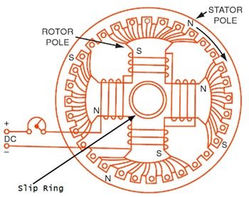
Ques.77. The maximum speed variation in a synchronous motor is
- Zero✓
- 5%
- 2%
- 10%
Ques.78. In a synchronous motor which loss varies with the load?
- Windage loss
- Bearing friction Loss
- Core Loss
- Copper Loss✓
In the rotating machine whether it is AC or DC machine the type of losses are almost same Cooper- loss(I2R) Losses:- All windings have some resistance (though small) and hence there are copper losses associated with current flow in them. The copper loss can again be subdivided into stator copper loss, rotor copper loss, and brush-contact loss. The stator and rotor copper losses are proportional to the current squared and are computed with the dc resistance of windings at 75°C. The conduction of current between the brushes (made of carbon) and the commutator of a dc machine is via short arcs in the air gaps which are bound to exist in such a contact. As a consequence, the voltage drop at the brush contact remains practically constant with the load; its value for positive and negative brushes put together is of the order of 1 to 2 V. The brush-contact loss in a dc machine is therefore directly proportional to current. The contact losses between the brushes (made of copper-carbon) and slip-rings of a synchronous machine are negligible for all practical purposes. Copper-losses are also present in field windings of synchronous and dc machines and in regulating the rheostat. However, only losses in the field winding are charged against the machine, the other being charged against the System. Stray load Losses:- Apart from the variable losses mentioned above, there are some additional losses that vary with the load but cannot be related to the current in a simple manner. These losses are known as “stray-load loss”.The stray-load loss is difficult to calculate accurately and therefore it is taken as 1 % of the output for a dc machine and 0.5% of the output for both synchronous and induction machines.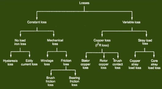
Ques.79. In a synchronous Motor, the damping winding is generally used to
- Provide starting torque
- Prevent hunting and provide starting Torque✓
- Reduces the eddy current
- Reduces the Noise Level
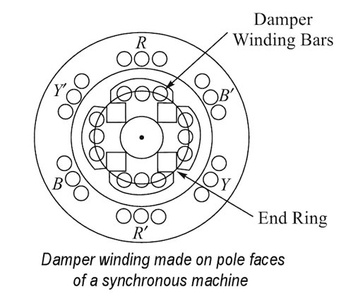
To enable the synchronous machine to start independently as a motor, a damper winding is made on pole face slots. Bars of copper, aluminum, bronze, or similar alloys are inserted in slots made or pole shoes as shown in Fig. These bars are short-circuited by end-rings on each side of the poles. Thus these short-circuited bars form a squirrel-cage winding. On application of a three-phase supply to the stator, a synchronous motor with damper winding will start at a three-phase induction motor and rotate at a speed near to synchronous speed. Now with the application of dc excitation to the field windings, the rotor will be pulled into synchronous speed since the rotor pole is now rotating at only slip-speed with respect to the staler rotating magnetic field. During Hunting, the rotor of the synchronous motor starts to oscillate in its mean position, therefore, a relative motion exists between damper winding and hence the rotating magnetic field is created. Due to this relative motion, e.m.f. gets induced in the damper winding. According to Lenz’s law, the direction of induced e.m.f. is always so as to oppose the cause producing it. The cause is hunting. So such induced e.m.f. oppose the hunting. The induced e.m.f. tries to dampen the oscillations as quickly as possible. Thus hunting is minimized due to damper winding.Use of Damper Winding to Provide the starting torque
Use of Damper winding to prevent Hunting
Ques.80. In transmission lines generally the wire used are
- ACSR wires✓
- Copper wires
- Iron wires
- Aluminum wires
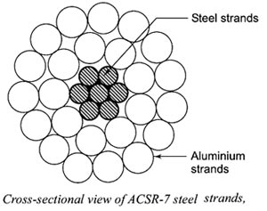
In transmission lines generally the wire used are ACSR wires. Steel-cored aluminum (ACSR): For transmission of high voltages, multi-stranded (composite conductors, such as stranded copper conductors, hollow copper conductors, and aluminum conduct steel reinforced (ACSR) are used. An ACSR conductor has a central core of galvanized steel wire covered with successive layers of aluminum strands, which are electrically in parallel. Because of galvanized steel wire, the tensile strength of the conductor is increased, so that the sag is reduced. It reduces the tower height and is useful for increasing the span length. Another advantage of the ACSR is that the diameter of the conductor may be increased so that the effect of the corona is less. The cross-sectional view of such a conductor is shown in Fig..When compared with the equivalent copper conductor. the breaking strength of ACSR is high, whereas its weight is less. For a large span. the number of transmission line supports required will be reduced. Therefore, the cost of support, foundation, insulators, erection, and at the same time, the cost of maintenance is reduced. The ACSR conductors have the following advantaged