Ques.81. Which one of the materials is used to fix the screw on the concrete wall and ceiling?
- Link clips
- Bushings
- Saddles
- Rawl Plug✓
Cavity Fixings are used to create reliable fixings into hollow walls and ceilings. Rawlplug’Uno’ Plugs have a universal function. Their patented zigzag expansion pattern allows them to form a secure fixing into hollow walls, or any other type of wall, ceiling or floor. They are suitable for all light to medium weight applications and are color-coded in Yellow, Red, and Brown for screw gauges ranging from 3.0 mm to 6.0 mm, with plug lengths of 24, 28, 30 and 32 mm. Corresponding drill holes are 5, 6, 7, and 8 mm in diameter.
Ques.82. Which type of insulation covers the conductor is used for low voltages?
- Polyvinyl Chloride(P.V.C)
- Paper
- Vulcanized Indian Rubber
- Cotton and silk Insulation✓
Insulating Materials:- The various insulating materials used in cables are as follows: Silk and Cotton:– These types of insulation materials are used on conductors which are used for low voltage purposes. These insulated wires are usually used for instrument and motor winding. Polyvinyl Chloride (PVC):- It is a synthetic compound material and comes as a white odorless, tasteless, chemically inert, non-inflammable, and insoluble powder. It is combined chemically with a plastic compound and is wed over the conductor as an insulation cover. PVC has good dielectric strength and a dielectric constant of 5. Its maximum continuous temperature rating is 75° C. It is inert to oxygen and almost chemically stable, so it is preferred over VIR cable &. PVC insulated cables are usually employed for medium and low-voltage domestic, industrial lights, and power installations. Vulcanized India Rubber (VIR) is useful for low-voltage power distribution systems only, because of its small size. It is prepared by mixing Indian rubber with mineral matter such as sulfur, zinc oxide, red lead, etc. It has a reasonable value of dielectric strength (15 kV/mm). Its use is limited because of its low melting point, low chemical resistance capability, and short span of life. The advantage of using vulcanized India rubber is that when it is used for a cable, the cable becomes stronger and more durable. It can withstand high temperatures and remain more elastic than pure rubber. The drawback of using this material for insulation is that it attacks copper. Hence, before using VIR as insulation, the copper conductor must be tinned well. Impregnated Paper:- This is used as an insulator in the case of power cables because it has low capacitance, high dielectric strength (30 kV/mm), and is economical. The paper is manufactured with wood pulp, rags, or plant fiber by a suitable chemical process. It has high resistance due to high resistivity under dry conditions. The drawback of this cable is that it absorbs a small amount of moisture only, which reduces the insulation resistance. Therefore, a paper insulated cable always requires some sort of protective covering and it is impregnated in insulating oil before use.
Ques.83. The cheapest system of wiring is
- Casing and capping
- Cleat Wiring✓
- Batten Wiring
- Conduit Wiring
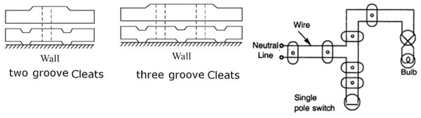
Electrical wiring is done in residential and commercial buildings to provide power for lights, fasts, pumps, and other domestic appliances known as domestic wiring. There are several wiring systems in practice such as tree systems and distribution systems. The cheapest system of wiring is Cleat Wiring. Types Of wiring The following are the different types of wiring systems used for domestic electrical installation. This system of wiring is the cheapest one. This system is used for insulated cables like rubber insulated cable, PVC cable etc. The cables are run over cleats made of porcelain. The cleats are generally in pairs having the bottom and top halves. The bottom half is grooved to receive the wire and the top is for cable grip. Initially, the bottom and top cleats are fixed on the wall loosely according to the layout. Then the cable is drawn, tensioned and the cleats are tightened by a screw. Cleats are fixed at regular intervals not exceeding 0.6 m Apart. This wiring is suitable for temporary installations where cost is the main criterion.
Cleat Wiring
Advantages of Cleat Wiring:
Disadvantages of Cleat Wiring:
Ques.85. Bucholz relay is operated by
- Eddy currents
- Gas pressure✓
- Electromagnetic Induction
- Electrostatic Induction
The Buchholz relay is a gas-operated relay used for the protection of oil-immersed transformers against all types of internal faults. The slow-developing faults called incipient faults in the transformer tank below oil level operate Buchholz relay which gives an alarm. If the faults are severe it disconnects the transformer from the supply. It uses the principle that due to the faults, oil in the tank decomposes, generating the gases. The 70% component of such gases is hydrogen which is light and hence rises upwards towards the conservator through the pipe. The Buchholz relay is connected to the pipe, as shown in Fig. Due to the gas collected in the upper portion of the Buchholz relay, the relay operates and gives an alarm. There are many types of internal faults such as insulation fault, core heating, bad switch contacts, faulty joints etc. which can occur. When the fault occurs the decomposition of oil in the main tank starts due to which the gases are generated. As mentioned earlier, the major component of such gases is hydrogen. The hydrogen tries to rise up towards the conservator but in its path, it gets accumulated in the upper part of the Buchholz relay. When gas gets accumulated in the upper part of the housing, the oil level inside the housing falls. Due to this the hollow float tilts and closes the contacts of the mercury switch attached to it. This completes the alarm circuit to sound an alarm. Due to this operator knows that there is some incipient fault in the transformer. The transformer is disconnected and the gas sample is tested. The alarm circuit does not immediately disconnect the transformer but gives the only indication to the operator. This is because sometimes bubbles in the oil circulating system may operate the alarm circuit though there is no fault. However, if a serious fault such as an internal short circuit between phases, earth fault inside the tank, etc. occurs then a considerable amount of gas gets generated. Thus due to the fast reduce the level of oil, the pressure in the tank increases. This energizes the trip circuit which opens the circuit breaker. Thus transformer is totally disconnected from the supply. The connecting pipe between the tank and the conservator should be as straight as possible and should slope upwards the conservator at a small angle from the horizontal This angle should be between 10 to 11° For the economic considerations, Buchholz relays are not provided for the transformers having a rating below 500 kVA. Advantages The various advantages of the Buchholz relay are, Normally a protective relay does not indicate the appearance of the fault. It operates when a fault occurs. But Buchholz relay gives an indication of the fault at the very early stage, by anticipating the fault and operating the alarm circuit. Thus the transformer can be taken out of service before any type of serious damage occurs. It is the simplest protection in the case of transformer. Limitations The various limitations of the Buchholz relay are,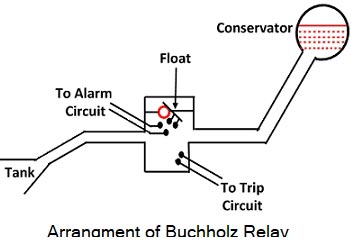
Ques.86. The main consideration in designing feeders is
- Current carrying capacity✓
- Voltage Drop
- Resistance
- Transmission Voltage
DESIGN CONSIDERATIONS IN A DISTRIBUTION SYSTEM Good voltage regulation is the most important factor in a distribution system for delivering good service to the consumer. For this purpose, careful consideration is required for the design of feeders and distributor networks. Feeders:- Feeders are the conductors that connect substations to consumer ports and have a large current-carrying capacity. The current loading of a feeder is uniform along the whole of its length since no lappings are taken from it. The design of a feeder is based mainly on the current that is to be carried. Distributors:- Distributors are the conductors, which run along a street or an area to supply power to consumers. These can be easily recognized by the number of tappings, which are taken from them for the supply to various consumer terminals. The current loading of a distributor is not uniform and it varies along the length while its design is largely influenced by the voltage drop along with it. Service Main and Sub Main:- Thc service mains are the conductors forming connecting links between distributors and metering points of the consumer’s terminal The term sub-main refers to the several connections given to consumers from one service main. The area of the cross-section of a sub-main conductor is greater than that of the service mains.
Ques.87. The speed of the ceiling fan is about
- Upto 10 RPM
- Upto 200 RPM
- Upto 450 RPM✓
- Upto 10000 RPM
Ques.88. The air preheater in a thermal power plant is called as
- Safety Device
- Efficiency increasing equipment✓
- Starting Device
- Very essential Device
The air preheater in a thermal power plant is called efficiency increasing equipment. Air Preheaters The heat carried with the ‘flue gases coming out of the economizer is further utilized for preheating the air before supplying it to the combustion chamber. It has been found that an increase of 20°C in the air temperature increases the boiler efficiency by 1%. The air heater is not only considered in terms of boiler efficiency in modern power plants but it is also considered as necessary equipment for the supply of hot air for drying the coal in pulverized fuel systems to facilitate grinding and satisfactory combustion of fuel in the furnace The use of a preheater is much more economical when used with pulverized fuel boilers because the temperature of flue gases going out is sufficiently large and high air temperature (250-350°C) is always desirable for better combustion. Air heaters are usually installed in steam generators that burn solid fuels but rarely on gas o air-fired units. By contrast, economizers are specified for most boilers burning liquid or gas or coal whether or not an air heater is provided. Recuperative or static and regenerative preheaters are used commonly. In the recuperative type, the flue gas passes through bundles of steel tubes and the air flows surrounding the tubes. In the regenerative type, air and flue gases flow on both sides of a slow-moving drum made of corrugated metal plates. The principal benefits of preheating the air are the following: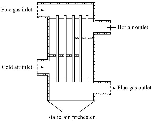
Ques.89. In the synchronous motor, damper winding is placed at
- Stator
- Rotor✓
- Both Stator and Rotor
- Yoke
To enable the synchronous machine to start independently as a motor, a damper winding is placed on rotor pole face slots. Bars of copper, aluminum, bronze, or similar alloys are inserted in slots made or pole shoes as shown in Fig. These bars are short-circuited by end-rings on each side of the poles. Thus these short-circuited bars form a squirrel-cage winding. On application of a three-phase supply to the stator, a synchronous motor with damper winding will start at a three-phase induction motor and rotate at a speed near to synchronous speed. Now with the application of dc excitation to the field windings, the rotor will be pulled into synchronous speed since the rotor pole is now rotating at only slip-speed with respect to the staler rotating magnetic field. During Hunting, the rotor of the synchronous motor starts to oscillate in its mean position, therefore, a relative motion exists between damper winding, and hence the rotating magnetic field is created. Due to this relative motion, e.m.f. gets induced in the damper winding. According to Lenz’s law, the direction of induced e.m.f. is always so as to oppose the cause producing it. The cause is hunting. So such induced e.m.f. oppose the hunting. The induced e.m.f. tries to dampen the oscillations as quickly as possible. Thus hunting is minimized due to damper winding.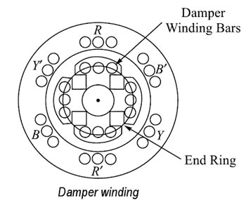
Use of Damper winding to prevent Hunting
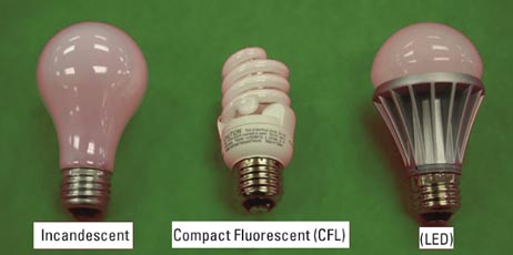
Ques.90. LED lamps have a general life expectancy of
- 1000 hrs
- 5000 hrs
- 15000 hrs
- 50000 hrs✓
Light-emitting diode (LED) Light-emitting diode (LED) lamps arc fairly new to the general illumination scene. As technology continues to improve, they will become a great option. Incandescent lamps Incandescent lamps have been around for a long time and are still commonly used, but they don’t perform as well as some of the other lamps on the market. Compact fluorescent (CFL) Compact fluorescent (CFL) lamps are becoming more popular.