
SSC JE Electrical Conventional Paper with Explained Solution 2016-17 | MES Electrical
Ques 1. A conducting wire has a resistance of 5Ω. What is the resistance of another wire of the same material but having half the diameter and four times the length?
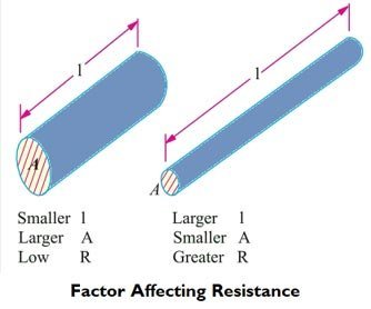
Factors Affecting the Resistance
The resistance R offered by a conductor depends on the following factors :
- Length of the material (l): The resistance of a material is directly proportional to the length. The resistance of the longer wire is more.
- Cross-Section Area (a): The resistance of a material is inversely proportional to the cross-sectional area of the material. More cross-sectional area allowed the passage of more number of electrons offering less resistance.
- Nature of Material: As discussed earlier the conductor has a large number of free electrons hence it offers less resistance whereas Inductor has less number of free electrons hence it offers more resistance.
- Temperature: The temperature of the material affects the value of the resistance. In General case, the resistance of the material increases as its temperature increases.
So for any given material at a certain given temperature, the resistance is given as
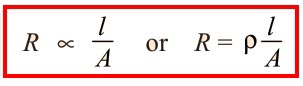
l = Length in Meter
A = area of cross-section in m2
R = Resistance in Ohm
Now suppose
Resistance of the first conductor be R1= 5Ω
Length = L1,
Area = A1
Resistance of the second conductor = R2,
Length = L2
Area = A2
Given L2 = 4L1
A2 = A1/2
[latex]\begin{array}{l}{R_1} = \rho \dfrac{{{L_1}}}{{{A_1}}}\\\\{R_2} = \rho \dfrac{{{L_2}}}{{{A_2}}}\end{array}[/latex]
Dividing both the equation
[latex]\begin{array}{l}\dfrac{{{R_2}}}{{{R_1}}} = \dfrac{{{L_2}}}{{{A_2}}} \times \dfrac{{{A_1}}}{{{L_1}}}\\\\\dfrac{{{R_2}}}{{{R_1}}} = \dfrac{{{L_2}}}{{{L_1}}} \times \dfrac{{{A_1}}}{{{A_2}}} = \dfrac{{{L_2}}}{{{L_1}}} \times \frac{{\left( {\dfrac{{\pi {d_1}^2}}{4}} \right)}}{{\left( {\dfrac{{\pi {d_2}^2}}{4}} \right)}}\\\\\dfrac{{{R_2}}}{{{R_1}}} = \dfrac{{{L_2}}}{{{L_1}}} \times {\left( {\dfrac{{{d_1}}}{{{d_2}}}} \right)^2} = \dfrac{4}{1} \times {\left( {\dfrac{2}{1}} \right)^2}\\\\\dfrac{{{R_2}}}{5} = 16\\\\{R_2} = 80\Omega \end{array}[/latex]
Ques 2. Two coils connected in parallel across a 100V DC supply, take 10 A current from the supply. Power dissipated in one coil is 600 W. What is the resistance of each coil?
Effective Resistance of R1 and R2 = R1 + R2
Since the resistance is connected in the series therefore there effective resistance is
REffective = R1R2/(R1 + R2)
100V/10A = R1R2/(R1 + R2)
10Ω = R1R2/(R1 + R2)……………..(1)
Let power dissipated from resistance R1 be 600 W
Now Power P1 = V2/R1
= 600 = 1002/R1
or R1 = 16.67 Ω
Putting the value of R1 in equation 1
[latex]\begin{array}{l}10 = \dfrac{{16.67 \times {R_2}}}{{16.67 + {R_2}}}\\\\166.7 + 10{R_2} = 16.67{R_2}\\\\{R_2} = \dfrac{{166.7}}{{6.67}} = 25\Omega \end{array}[/latex]
Ques 3. Determine the current through 5Ω resistor in the given circuit
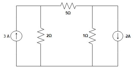
Sol:- The above circuit can be reconstructed using source transformation theorem
According to source transformation Theorem, a voltage source with a series resistor can be converted into an equivalent current source with a parallel resistor. In a similar manner, using Thevenin theorem, a current source with a parallel resistor can be represented by a voltage source with a series resistor. These transformations are called source transformations.
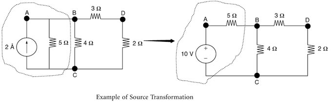
Now By applying source transformation in the above Question the given circuit will become
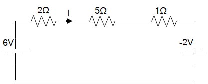
Now by applying KVL
-6 + 2I + 5I + 1I – (-2) = 0
8I = 4
I = 0.5A
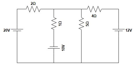
Ques 4. Find the voltage across 5Ω resistance in the network shown in figure using Thevenin’s theorem
Sol:- To determine the Thevenin’s Equivalent circuit Resistance Rth, all the voltage source are replaced by the Short circuit.
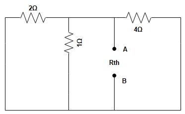
Rth = 2Ω || 1Ω || 4Ω
[latex]\begin{array}{l}{R_{th}} = \dfrac{1}{2} + \dfrac{1}{1} + \dfrac{1}{4} = \dfrac{7}{4}\\\\{R_{th}} = 0.571\Omega \end{array}[/latex]
To determine the voltage Vth the 5Ω Resitance is removed as shown in figure, Now by applying Node analysis method
[latex]\begin{array}{l}\dfrac{{{V_{th}} – 20}}{2} + \dfrac{{{V_{th}} + 10}}{1} + \dfrac{{{V_{th}} – 12}}{4} = 0\\\\2{V_{th}} – 40 + 4{V_{th}} + 40 + {V_{th}} – 12 = 0\\\\7{V_{th}} = 12\\\\{V_{th}} = 1.714V\end{array}[/latex]
The equivalent Thevnin’s circuit is shown below
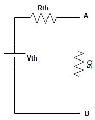
Now by applying the voltage divider rule, the voltage across the 5Ω will be
[latex]\begin{array}{l}{V_{AB}} = {V_{Th}} \times \dfrac{{{R_{th}}}}{{{R_{th}} + R}}\\\\{V_{AB}} = 1.714 \times \dfrac{5}{{5 + 0.571}}\\\\{V_{AB}} = 1.538\end{array}[/latex]