
Ques 2a. An aeroplane with a wing span of 52 meters is flying horizontally at 1100 km/h. If the vertical component of the earth’s magnetic field is 38 × 10-6 T, find the EMF generated between the wings-tips.
Sol:- Relevant equations
The emf induced in a straight conductor of length l moving with velocity v perpendicular to a magnetic field B is
E =Blvsinθ
Where
E is the generated voltage
B is the magnetic flux density
l is the length of a conductor in the magnetic field
v is the velocity of the conductor perpendicular to the magnetic lines.
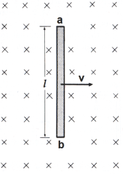
- The area swept by conductor in 1 second = lv
- The flux cut by conductor in 1 second = Blv
- Then the emf induced in a straight conductor of length l moving with velocity v perpendicular to a magnetic field B is
E = Blvsinθ - The value of sinθ is maximum at 90 degrees i.e When the coil is perpendicular to the field axis. i.e E = Blv
- Where B,l, and v are mutually perpendicular to each other
Length of Aeroplane wings is l = 52 Metre
Velocity of aeroplane is v = 1100 Km/h
Now converting the Km/h in meter per second
[latex]v = 1100 \times \dfrac{5}{{18}} = 305.6{\text{ }}m/s[/latex]
Vertical component of magnetic field B is = 38 × 10–6 Tesla
Generated EMF E = Blv sinθ
38 × 10-6 × 52 × 305.6 × sin90°
E = 38 × 10-6 × 52 × 305.6 × 1
= 0.6038 V
Ques 2b: A coil of 200 turns is wound uniformly over a wooden ring having a mean circumference of 60 cm and a uniform cross-sectional area of 500 mm2. If the current through the coil is 4 A, calculate the (i) magnetic field strength, (ii) flux density, and (iii) total flux
Ans 2b: Relevant Theory
Magnetic Field Strength (H) gives the quantitative measure of strongness or weakness of the magnetic field.
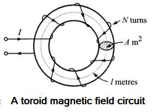
Suppose that a current of I amperes flows through a coil of N turns wound on a toroid of length I meters. The mmf is the total current linked to the magnetic circuit i.e IN ampere-turns. If the magnetic circuit is homogeneous and of the uniform cross-sectional area, the mmf per meter length of the magnetic circuit is termed as the magneticfield strength, magnetic field intensity, or magnetizing force. It is represented by symbol H and is measured in ampere-turns per meter (At/m).
[latex display=”true”]H = \dfrac{\mathbb{F}}{L} = \frac{{IN}}{l}[/latex]
Note:- Magnetic field intensity, H, is independent of the medium. Its value depends only on the number of turns N and the current I flowing in the coil.
(i) Now in the above question, the given Quantities are
N = 200
l = 60 cm = 0.6 m
A = 500 mm2
I = 4 A
[latex]H = \dfrac{{IN}}{l} = \dfrac{{200 \times 4}}{{0.6}} = 1333.3{\text{ At/m}}[/latex]
(ii) Relevant theory
Magnetic flux density (B) is defined as the magnetic flux per unit area of a surface at the right angle to the magnetic field. This is also known as magnetic induction. Its symbol is B and measured in Weber per square-meter or Tesla.
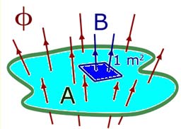
Φ = B.A(wb)
B = Φ/A (Tesla)
Where Φ = magnetic field
B = Flux density
A = Surface area
Relation Between Magnetic Flux Density and Field Intensity
At any point in a magnetic field, field strength or field intensity H is the force maintaining the magnetic flux and producing a particular value of flux density B at that point. Hence the field intensity H is the cause and the flux density B the effect. Thus the flux density can be assumed proportional to field intensity in the magnetic field i.e. in free space,
B=μoH
where μo is called permeability of free space or magnetic space constant. Its value is 4π × 10-7 H/m,
The flux density B also depends upon the nature of the medium. Thus the relative permeability of medium is μr, flux density at any point in a magnetic field is given by
B = μrμoH
The flux density.
B = μrμoH
= 4π × 10-7 × 1 × 1333.33
= 1.67 × 10⁻³ Tesla
(iii) Total Flux
Φ = B.A
= 1.67 × 10-3 × 500 × 10-6
= 0.8375 μWb
Ques 2(c). An iron choke takes 4 A current when connected to a 20 V dc supply. When connected to a 65 V, 50 Hz ac supply, it takes 5 A current. Determine the power drawn by the coil.
Sol- The iron choke has both resistance R and inductance L. When connected to a dc supply, only its resistance is effective in limiting the current; when connected to an ac supply, its impedance becomes effective in limiting the current.
When DC supply is connected
i = 4 A
V = 20 Volt
When AC supply connected
I = 5 A
v = 65 Volt, 50 Hz
Resistance of coil
[latex]R = \dfrac{V}{I} = \dfrac{{20}}{4} = 5\Omega[/latex]
Power dissipated by the coil is = I2R = 52 × 5
P= 25 × 5 = 125 W
Ques 2(d): Define the following terms :
(i) Mutual inductance
(ii) Resonance
(iii) MMF
(iv) Q-factor
Ans(i)
Mutual Inductance:
Mutual induction is the property of two coils by virtue of which each opposes any change in the current flowing in the other by developing an induced emf.
or
Mutual induction is the phenomenon of production of induced emf in one coil due to the varying current in the neighboring coil.
The unit of mutual inductance is Henry.
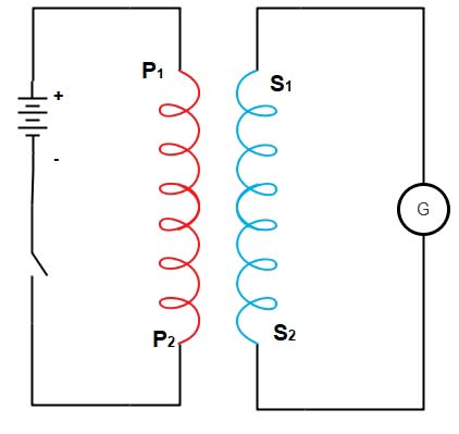
- Let us consider two coils P1P2 and S1S2 placed close to each other.
- The two coils are magnetically coupled but act as a separate circuit.
- The coil P1P2 is the primary coil connected to a battery through a switch.
- The coil S1S2 is the secondary coil connected to a galvanometer.
- The two circuits are said to be coupled circuits. When the switch is pressed, the pointer of the galvanometer gives a sudden kick in one direction, say to the Right. When the key is released, the galvanometer will give deflection to the left.
Working:
- When the switch is closed, the current in the primary begins to increase from zero to maximum. During the growth of current, the magnetic flux linked with the primary begins to increase.This sets up an induced current in the secondary.
- According to Lenz’s law, the direction of induced current in the secondary is such as to oppose the growth of current in the primary. The deflection of the galvanometer is due to the induced
current in the secondary. - When the switch is open, the current in the primary coil begins to decrease from maximum
to zero. So, the magnetic flux linked with the primary as well as the magnetic flux linked with the secondary begins to decrease. Due to the decrease of magnetic flux linked with the secondary, an induced current is set up in the secondary. - According to Lenz’s law, the direction of the induced current should be such as to oppose the decay of battery current in the primary.
- This is possible only if the induced current flows in the same direction as the current in the primary.
- This explains as to Why galvanometer gives deflection to the left at the time of break of the circuit.
Note. The induced current is developed in the secondary on account of mutual induction. Simultaneously, a self-induced emf develops in the primary also. So, self-induction and mutual induction occur simultaneously. The mutual inductance is always positive but mutually induce voltage may be positive or negative depending upon the direction of the reference current.
Factors affecting the mutual inductance of two adjacent coils include the following:
- Physical dimensions of the two coils
- Number of turns in each coil
- Distance between the two coils
- Relative positions of the axes of the two coils
- Permeability of the cores
(ii) Resonance
Resonance is the condition that exists in ac circuits under the steady state when the input current is in phase with the input voltage. When in resonance, the ac circuit is purely resistive and draws power at unity power factor. The condition of resonance can be obtained by connecting an inductor and a capacitor in series (or in parallel across an ac voltage source of variable frequency. At resonance, the impedance of the circuit is minimum (or maximum). Hence, for a given applied voltage the current becomes maximum (or minimum).
or
In an electrical circuit, the condition that exists when the inductive reactance and the capacitive reactance are of equal magnitude, causing electrical energy to oscillate between the magnetic field of the inductor and the electric field of the capacitor, this phenomenon is termed as resonance.
Resonance occurs because the collapsing magnetic field of the inductor generates an electric current in its windings that charges the capacitor and the discharging capacitor provides an electric current that builds the magnetic field in the inductor, and the process is repeated.
Application of Resonance
- Creating oscillations useful as a source of the carrier signal in Transmitters.
- Sensing the presence of a particular frequency in the received signals.
- Radio, TV, communication systems as also HV line carrier communication systems use resonance
- A resonant circuit can be used to “block” (present high impedance toward) a frequency or range of frequencies, thus acting as a sort of frequency “filter” to strain certain frequencies out of a mix of others. In fact, these particular circuits are called filters,
- It is possible to get very high voltages with small voltage using near resonance values of L and C.
(iii) Magnetomotive force
“Magnetomotive force is any physical cause that produces magnetic flux. It is analogous to electromotive force or voltage in electricity.
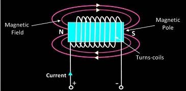
The standard definition of magnetomotive force involves current passing through an electrical conductor, which accounts for the magnetic fields of electromagnets. Permanent magnets also exhibit magnetomotive force, but for different reasons.
The unit of magnetomotive force is the Ampere-Turn (AT), represented by a steady, direct electric current of one ampere flowing in a single-turn loop of electrically conducting material in a vacuum.
The Gilbert (Gi), is the CGS unit of magnetomotive force.The unit is named after William Gilbert, an English physician, and natural philosopher.
The strength of the MMF is equivalent to the product of the current around the turns and the number of turns of the coil. As per work law, The MMF is defined as the work done in moving the unit magnetic pole (1weber) once around the magnetic circuit. The magnetomotive force in an inductor is given by
M.M.F = N × I AT
where N is the number of turns of the coil
I is the current in the coil.
The MMF is also known as the magnetic potential. It is the property of the material to give rise the magnetic field. The relation between flux, Reluctance, and magnetic Force is
M.M.F = ΦR
Where Φ is the magnetic flux and
R is the magnetic reluctance (Resistance to magnetization offered by the Iron Core to set up the flux)
Hence the magnetomotive force is directly proportional to the magnetic flux and the magnetic reluctance.
(iv) Q-factor
Quality factor or circuit magnification factor (Q) is defined as,
[latex display=”true”]Q = 2\pi \dfrac{{Maximum{\text{ }}energy{\text{ }}stored}}{{Energy{\text{ }}dissipated{\text{ }}per{\text{ }}cycle}}[/latex]
Maximum energy stored = Electromagnetic energy in Inductor or Electrostatic Energy in Capacitor
[latex]=\dfrac{1}{2}L{{\mathop{\rm I}\nolimits} _{\max }}^2{\text{ or }}\dfrac{1}{2}C{V_{\max }}^2[/latex]
Therefore,
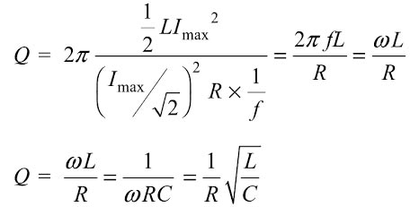
Thus, Q is inversely proportional to R. Hence, for series RLC circuit, a high value of quality factor implies low losses and a low value of Q implies high losses.
Also, the quality factor for a circuit is defined as
[latex display=”true”]Q = \dfrac{{Resonant{\text{ }}frequency}}{{Bandwidth}} = \dfrac{{{\omega _o}}}{{{\omega _1} – {\omega _2}}}[/latex]
The selectivityof the circuit is defined as the reciprocal of quality factor, i.e
[latex display=”true”]selectivity = \dfrac{1}{Q} = \frac{{Bandwidth}}{{Resonant{\text{ }}frequency}} = \dfrac{{{\omega _1} – {\omega _2}}}{{{\omega _o}}}[/latex]
Therefore, a circuit will be highly selective if it has a high value of Q. For a series RLC circuit,
a high value of the quality factor implies a narrow resonant peak and a low value of Q implies
broad resonant peak. The variations of magnitude and phase angle of current in an RLC series
circuit for different values of quality factor (Q).