
SSC JE Electrical Conventional Paper with Explained Solution 2016 | MES Electrical
Qus 1(a). Two conductors, one of copper and the other Iron, are connected in parallel and carry equal current at 30°C. What proportion of the current will pass through each if the temperature raised to 90°C? The temperature coefficient of resistance at 0°C is 0.0043/°C and 0.0063/°C for copper and iron respectively.
Sol:- Let the Resistance of the copper be Rcu
& The resistance of the Iron be Ri
Resistance Temperature Coefficient
Rt = Ro(1 + αo[t2 – t1])
Where
Ro is the temperature at 0° Celsius
Rt is the temperature at t° Celsius.
Since the copper and iron conductors carry equal currents at 25°C, their resistances are the same at that temperature. Let each be R ohm i.e
Rcu = Ri = R
At 90°C, resistance of copper conductor
Rt1 = R[ 1 + 0.0043(90 – 30)]
Rt1 = R[ 1 + 0.0043 × 60]
Rt1 = 1.258 R
At 90°C, resistance of iron conductor
Rt2 = R[ 1 + 0.0063(90 – 30)]
Rt2 = R[ 1 + 0.0063 × 60]
Rt2 = 1.378 R
If I is the current at 90°C, then as per current divider rule, current in the copper conductor is
[latex]\begin{array}{l}{I_1} = I\dfrac{{{{\rm{R}}_{\rm{2}}}}}{{{R_1} + {R_2}}}\;\\\\ = I\dfrac{{1.378R}}{{1.258R + 1.378R}} = 0.522I\end{array}[/latex]
Now current in Iron conductor at 90°C
[latex]{I_2} = I\dfrac{{{{\rm{R}}_{\rm{2}}}}}{{{R_1} + {R_2}}} = I\dfrac{{1.258R}}{{1.258R + 1.378R}} = 0.477I[/latex]
Hence, the copper conductor will carry 52.23% of the total current and iron conductor will carry the
balance i.e. 47.7%.
Ques 1(b). Determine the resistance and the power dissipation of a resistor that must be placed in series with a 50-ohm resistor across a 220 V source in order to limit the power dissipation in the 50 Ohm resistor to 200 watts.
Ans.1(b). The diagram of the above question is given below
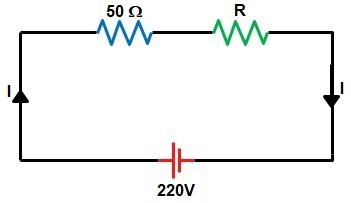
[latex]Current{\text{ I}} = \left( {\dfrac{{220}}{{\left( {50 + R} \right)}}} \right)[/latex]
Power dissipation in the resistor
P = I2 × R
Now the power dissipation in the 50Ω resistor
P50 = I2 × R
[latex]\begin{array}{l}200 = {\left( {\dfrac{{220}}{{\left( {50 + R} \right)}}} \right)^2} \times 50\\\\{\left( {\dfrac{{220}}{{\left( {50 + R} \right)}}} \right)^2} = \dfrac{{200}}{{50}}\\\\{\left( {\dfrac{{220}}{{\left( {50 + R} \right)}}} \right)^2} = {\left( 2 \right)^2}\\\\\dfrac{{220}}{{\left( {50 + R} \right)}} = 2\end{array}[/latex]
220 = 2 × (50 + R)
2R = 220 – 100 = 120
R = 60Ω
Now power dissipation through R = 60Ω Resistance
P60 = I2R = I2 × 60
[latex]\begin{array}{l} = {\left( {\dfrac{{220}}{{\left( {50 + 60} \right)}}} \right)^2} \times 60\\\\ = {\left( {\dfrac{{220}}{{\left( {110} \right)}}} \right)^2} \times 60\\\\ = 4 \times 60 = 240{\text{ W}}\end{array}[/latex]
Hence R = 60 Ω and P = 240 W
Ques 1(c). In the network shown in figure 1, the different currents and voltages are as under:
i2 = 10 e-4t; i4 = 6 sint; v3 = 8 e-4t
Using Krichhoff’s Current Law find the Voltage V1.
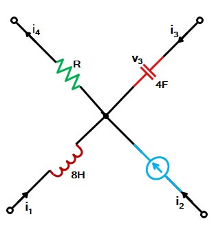
According to KCL, the algebraic sum of the currents meeting at juncion A is zero i.e.
i1 + i2 + i3 + (− i4 ) = 0
i1 + i2 + i3 − i4 = 0 ————–(i)
Now, current through a capacitor is given by i = C dv/dt
[latex]{i_3} = C\dfrac{{d{V_3}}}{{dt}} = \dfrac{{4d(8{e^{ – 4t}})}}{{dt}} = – 128{e^{ – 4t}}[/latex]
Substituting this value of i3 in Eq (i) above, we get
i1 + 10e-4t − 128e-4t − 6sint = 0
or
i1 = 118e-4t + 6sint
The voltage V1 developed across the coil is
[latex]\begin{array}{l}{V_1} = L\dfrac{{d{I_1}}}{{dt}} = 8.\dfrac{d}{{dt}}\left( {118{e^{ – 4t}} + {\rm{ }}6\sin t} \right)\\\\ = 8\left( { – 472{e^{ – 4t}} + 6\cos t} \right)\\\\ = \left( {48\cos t – 3776{e^{ – 4t}}} \right)\end{array}[/latex]
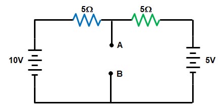
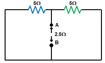
Ques 1d. From the given figure find the current in the 10 ohm resistor using Thevenin’s Theorem
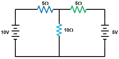
Sol:- The first step is to remove the 5Ω resistance, and to determine the voltage Vth as shown in the figure.
Next, the voltage between the two points where the load resistor used to be attached is determined. In this question, the original circuit with the load resistor removed is nothing more than a simple series circuit with opposing batteries, and therefore we can determine the voltage across the open load terminals by applying the rules of series circuits.i.e
V = IR
10 – 5 = 5I + 5I
5 = 10I
I = 0.5 A
Voltage across 5Ω Resistance
= 5 × 0.5 = 2.5 V
or
Vth = VAB = 10 − 2.5 = 7.5 V
The voltage between the two load connection points can be figured from one of the battery’s voltages and one of the resistor’s voltage drops and comes out to 11.2 volts. This is our “Thevenin voltage” (Vth) in the equivalent circuit.
⇒ To find the Rth, the two voltage source is removed and replaced with the short circuit. The resistance at Terminal AB then is in the parallel combination of the two 5Ω resistance.
[latex]{R_{th}} = \dfrac{{5 \times 5}}{{5 + 5}} = 2.5\Omega[/latex]
⇒ Now the Thevenin’s equivalent circuit is shown in the fig.
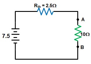
So current through 10Ω resistor
[latex]{I_{10}} = \dfrac{{7.5}}{{\left( {10 + 2.5} \right)}} = \dfrac{{7.5}}{{12.5}} = 0.6A[/latex]
Ques1(e). A variable air capacitor has 10 movable plates and 11 stationary plates. The area of each plates is 0.002 m2 and separation between opposite plates is 0.001 m. Determine the maximum capacitance of this variable capacitor.
Ans. Variable capacitors are constructed so that their capacitance value can be changed over a certain range. They generally contain a set of movable plates, which are connected to a shaft, and a set of stationary plate. The movable plates can be interleaved with the stationary plates to increase or decrease the capacitance.
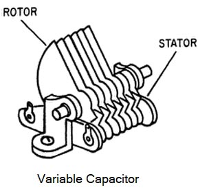
For maximum capacitance, the two groups of plate i.e stationary part and rotating part must face each other. The whole capacitor consists of (n – 1) identical single capacitors connected in parallel. Each capacitor has surface area A and plate separation d so its capacitance is given by
Co = εoA/d
Where
A = area of capacitor plate
d = distance
ε0 = the permittivity of free space = 8.854 × 10⁻¹²
[latex]\begin{array}{l}C = (n – 1){C_o} = \dfrac{{(n – 1){\varepsilon _o}A}}{d}\\\\ = \dfrac{{(21 – 1)(8.85 \times {{10}^{ – 12}})(0.002)}}{{0.001}}\\\\ = 0.354{\text{ nF}}\end{array}[/latex]