
Ques 6 (a). Explain earthing practices in brief
Ans:
Earthing:
The process of connecting metallic bodies of all the electrical apparatus and equipment to the huge mass of earth by a wire of negligible resistance is called earthing.
or
Earthing is to connect any electrical equipment to earth with a very low resistance wire, making it to attain earth’s potential. The wire is usually connected to a copper.
When a body is earthed, it is basically connected to the huge mass of earth by a wire having negligible resistance. Therefore, the body attains zero potential, that is, potential of the earth. This ensures that whenever a live conductor comes in contact with the outer body, the charge is released to the earth immediately.
Good Earthing must have low impedance enough to ensure that sufficient current can flow through the safety device so that it disconnects the supply ( <0.4 sec ). The fault current is much more than the full load current of the circuit which melts the fuse. Hence, the appliance is disconnected automatically from the supply mains.
According to Indian Electricity Rule No,61 the following equipment are to be connected to earth.
- The metal frame of motors, generators and other metallic parts of equipment are to be earthed.
- Earth terminals of the three pin lighting and power plug socket should be earthed.
- The metal casing of the portable apparatus like heater, electric iron, refrigerator, hair drier etc., should be earthed.
- All metal parts of the electrical installation such as metal conduits, light fittings, iron-clad main switches, iron-clad distribution, cable sheath etc., should be earthed.
The conductors used for earthing purposes are copper or galvanized iron wire. However since the conductor used for earthing must have high conductivity, copper is preferred. The conductor used should have sufficient diameter in order to carry the fault current safely. The earthing conductor should be installed in such a way that it should not get damaged or cut accidentally. It can be fixed to the equipment with the help of clamps and saddles. When fuses are used, the earth loop impedance should be low enough so as to allow 3 times the current on short circuit and 1.5 times the operating current when circuit breakers are used. The earth electrode should make very good contact with the general mass of the earth.
Methods of earthing:
Different methods of earthing are
- Wire or strip earthing
- Rod earthing
- Pipe earthing
- Plate earthing
Wire or strip earthing:
This system of earthing employs the use of 5 SWG (standard wire gauge) copper wire or strip of cross section not less than 25 mm x 1.6 mm. The strips o^] wires are buried in horizontal trenches. This type of earthing is used where the earth bet has a rocky soil and excavation work is difficult.
Earthing through water mains:
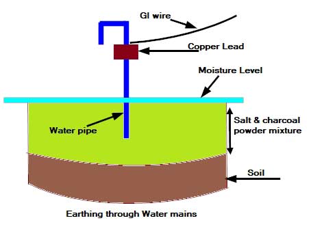
In this type of earthing, a stranded copper lead is used that is rounded on the pipe with the help of a steel binding wire and a properly designed earthing clip. The copper lead is soldered to make it solid. Before making the connection to the water mains it should be ensured that G.I. pipe is used throughout.
Earthing rods
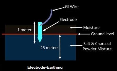
Earthing rods or ground electrodes are usually solid rods or pipes driven into the ground to make an earth connection, usually made of copper.A copper rod of 12.5mm (1/2 inch) diameter or 16mm (0.6in) diameter of galvanized steel or hollow section 25mm (1inch) of GI pipe of length above 1.5m (8.2 ft) are buried upright in the earth manually or with the help of a pneumatic hammer.It is the cheapest method of earthing and is employed in sandy areas.
Pipe earthing:
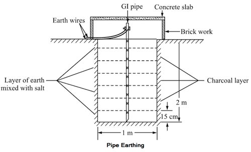
Taking into consideration, the factors such as initial cost, inspection, resistance measurement, etc., G.I. pipe earthing is the best form of ground connection. Iron is the cheapest material and remains serviceable even if put in the salty mass of earth. Pipe earthing is the common method of earthing done using G.l. of diameter 3.8 cm. A pit of about 40 cm square area and 2 to 5-meter depth is dug in the soil. To increase the dampness and moisture, charcoal and salt are filled in the pit in alternate layers up to about two meters from the bottom. An earth pipe can be protected from mechanical damage by covering it with cement concrete work. A funnel with mesh can also be provided to pour water.
The resistance of the earn connection measured between the earth electrode and any point in the wiring installation should be 1.0 Ω or lower for a good installation.
Plate Earthing:
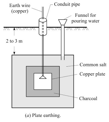
In the plate earthing a pit of about 3 melees depth is dug. The em electrode use may be a copper plate having a dimension 60 cm x 60 cm x 3.18 mm. (In case of GI plate, the dimension is 60 cm x 60 cm x 6.36 mm). After placing the electrode in the pit layers of charcoal and salt are used to fill the space around it.The layers of charcoal shall be placed immediately over the plate, and thereafter, successive layers of salt and charcoal are laid to keep the surroundings sufficiently moist.
Note: Pipe earthing and plate earthing is considered to be the best as they have a reasonably low value of earth resistance.
Advantages of Earthing:
- It protects the operating personnel from the anger of shock in case they come in contact with the charged frame due to defective insulation.
- It maintains the line voltage constant under unbalanced load condition.
- Protect the electrical equipment.
- Protect large buildings and all machines fed from overhead lines against lightning.
- Serve as a return conductor in electric traction system and communication.
- Avoid the risk of fire in an electrical installation system.
Ques 6 (b): With the help of neat and labeled circuit diagram, explain the process of electroplating.
Ans:
Electroplating
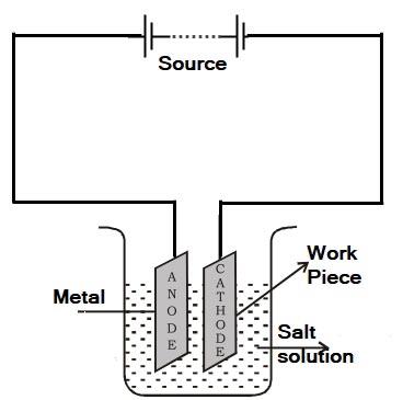
The term electroplating refers to the deposition of a metal on to the surface of another metal, alloy or any conductor in general, by the process of electrolysis. It consists of a process, by which a metal is deposited on another metal or alloy by passing a direct current through an electrolyte solution containing the metal ions to be deposited.
Therefore, electroplating can be defined as “a process in which a base metal is coated with a thin and uniform layer of another suitable metal by electrolytic deposition”.
The common coating metals used are Zn, Cu. Ni, Cr. Ag, Pt. Au, etc. Electrodeposition is an important and frequently used method in industries for metal coating.
Electroplating is a process of continuous flow of ions, which is not possible in Alternating current(due to changing in polarity very frequently) so the continue deposition of cation not occurs.
Process Involve in electroplating
The process involves the electroplating are:-
- Cleaning Operation
- Deposition of Metal
- Polishing and Buffing
- Periodic Reverse Current Process
- Polarization
- Throwing Power
- Post-Treatment
- Waste Disposal
Cleaning Operation: If electroplating is done on an under-greased and unclean surface, the deposit formed is not well adherent to the base metal and is likely to peel off. Therefore, to reduce the percentage of spoilage, great attention is given to cleaning operation.
Deposition of Metal: In all types of metal deposition processes, the article to be electroplated is made cathode, the solution is made up of salt of the metal to be deposited and an anode is often of the same metal which is to be deposited.
Polishing and Buffing: Silver, nickel or chromium plating requires polishing by mops driven at the peripheral speed of 2000 to 3000 m/minute. Mops may be of leather canvas or felt. It is very important to run these mops at high speeds indicated above. Lower speeds than this cause the mop to drag and the article becomes hot and burnishing, rather than polishing, an effect is obtained.
Periodic Reverse Current Process: According to this process, at regular intervals, plating current is reversed for a second or so.
Polarization: As electroplating current density is increased, the rate of deposition of metal is also increased up to the certain limit after which electrolyte surrounding the base metal becomes so much depleted of metal ions that rate of deposition does not increase with the increase in current density. If current density more than this limit, is employed, it will result in the electrolysis of water and hydrogen deposition on the cathode. This hydrogen evolved, blankets the base metal which diminishes the rate of metal deposition. This phenomenon is known as polarization. The blanketing effect can be reduced by agitating the electrolyte.
Throwing Power: It is defined as the ability of the electrolyte to produce even irregular surfaces.
Post-Treatment: While many jobs may be complete after the plating bath, others require a bit more love. For some metal coatings, an anti-tarnish or clear coat treatment is used in order to prevent tarnishing and improve resistance.
Waste Disposal – Post-Treatment and Waste Disposal is the final stage of the electroplating process.Electroplating can create hazardous materials. Having a green attitude on waste disposal not only keeps a shop in line with governmental regulations but also helps to keep the local community safe and pollution free. recycling the waste back into the plating process is a sign of a job well done.
Use of Electroplating:
- Building the thickness of metal surface
- Increasing wear resistance
- Increasing the electric conductivity-such as when plating a copper layer onto an electrical component.
- Preparing surfaces for enhanced adhesion prior to painting and e-coating
- Reduce friction
- Improve surface uniformity.
Ques 6 (c). How is the synchronous motor started? Explain the various methods of starting of a
synchronous motor in brief.
Ans:
Procedure for Starting a Synchronous Motor :
- First, main field winding is short-circuited.
- Reduced voltage with the help of auto-transformers is applied across stator terminals. The
motor starts up. - When it reaches a steady speed , a weak d.c. excitation is applied by
removing the short-circuit on the main field winding. If excitation is sufficient, then the machine will be pulled into synchronism. - The full supply voltage is applied across stator terminals by cutting out the auto-transformers.
- The motor may be operated at any desired power factor by changing the d.c. excitation.
Why is synchronous Motor Not self-starting?
- When a 3-phase balanced winding is supplied with 3 phase supply, a rotating magnetic field of constant magnitude and synchronous speed is produced.
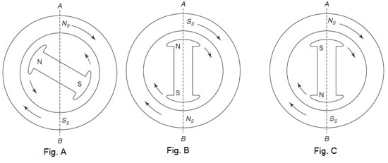
- Let the motor stator have 2-poles marked as Ns and S as shown in Fig. A.
- The stator poles are rotating at synchronous speed. Let us assume that it moves in the clockwise direction.
- The rotor is positioned as shown in Fig. B initially with reference to the position AB.
- As like pole repel, the rotor will tend to move in the anticlockwise direction.
- At the end of first half cycle o supply, the rotor poles occupy the position as shown in Fig. C with respect to the reference plane AB.
- Now, because of the attractive force between the unlike poles, the rotor will tend to move in the opposite, i.e. clockwise direction.
- So, with rapid movement of the stator poles, the rotor is subjected to a torque which is also rapidly reversing. But because of the inertia of the rotor, it will not respond to such a rapid reversing torque. So, the rotor remains stationary, which shows that it is not a starting Motor
METHODS OF STARTING SYNCHRONOUS MOTOR
The various methods to start the synchronous motor are,
- Using damper winding
- Using pony motors
- As a slip ring induction motor
- Using small d.c. machine coupled to it.
Using Damper Winding:
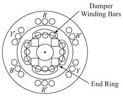 To enable the synchronous machine to start independently as a motor, a damper winding is made on pole face slots.
- Bars of copper, aluminum, bronze or similar alloys are inserted in slots made or pole shoes as shown in Fig
- These bars are short-circuited by end-rings or each side of the poles.
- Thus these short-circuited bars act as a squirrel cage winding.
- On application of three-phase supply to the stator, a synchronous motor with damper winding will start at 3- phase Induction motor and rotate at a speed near to synchronous speed.
- Now with the application of DC excitation to the field windings, the rotor will be pulled into synchronous speed since the rotor poles are now rotating at only slip-speed with respect to the stator rotating magnetic field.
- To limit the starting current drawn by the motor, a reduced voltage may be necessary, to apply for high capacity synchronous motors. Reduced voltage can be applied through an auto-transformer or through a star-delta starter.
- During starting period before the application of dc excitation, the field windings are kept closed through a resistor. DC is supplied from an independent source or through the armature of the do exciter, namely the dc generator carried on the shaft extension of the synchronous motor.
- If this is not done, a high voltage induced in the dc winding during starting period will strain the insulation of the field winding.
- Since starting of the synchronous motor is carried out as an induction motor, the starting torque developed is rather low and, therefore, large capacity motors may not be able to start at full load.
As a slip Ring Induction Motor
The above method of starting synchronous motor as a squirrel cage induction motor does not provide high starting torque. So to achieve this, instead of shorting the damper winding, it is designed to form a three-phase star or delta connected winding.
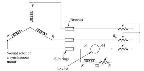
- For this method, the rotor of a synchronous motor must be a wound-rotor of 3-phase windings, similar to the stator windings of a synchronous or induction motor.
- The machine is started in a manner similar to that of a slip-ring induction motor by inserting variable resistances in the rotor circuit as shown in fig. If the synchronous motor has a built-in excitor on its shaft, then it can be connected in one of the phases of the rotor as shown in the figure.
- The resistors are included in the rotor as shown in the figure. The resistors are included in the rotor circuit at the time of starting and thereafter, they are slowly cut out as the rotor picks up speed.
- When the speed exceeds the critical value, the exciter builds up its DC voltage and the DC current from the exciter circuit magnetizes the rotor of the synchronous motor with the same number of poles as the stator.
- Consequently, by the time the starting resistors are short-circuited the machine will be running at full speed as an induction motor.
- The rotor is acted upon by two torques, namely, one unidirectional torque due to the induction motor action, and the second, a pulsating torque at slip frequency due to the rotating magnetic field produced by the stator currents.
- The slow relative motion of the staler mmf with respect to the motor enables the rotor to pull into synchronism, This type of starting is usually known as the synchronous-induction motor method of starting, and is useful when large starting torque is required at low starting currents.
Pony method:
In this method, the rotor is brought to the synchronous speed with the help of some external device like a small induction motor. Such an external device is called ‘Pony Motor’. Once the rotor attains the synchronous speed, the d.c. excitation to the rotor is switched on. Once the synchronism is established pony motor is decoupled. The motor then continues to rotate as a synchronous motor.
Using small d.c. machine
The synchronous motor can be started with the help of dc supply and dc compound motor, by coupling the synchronous motor to the dc motor. DC motor is started and the speed of the dc motor is adjusted by the speed regulator. The synchronous motor is then excited and synchronized with the ac supply mains. At the moment of synchronizing, the synchronous motor is switched on with the ac mains and the dc motor is disconnected from the dc supply mains. Now the synchronous machine operates as a synchronous motor and dc motor which helped to start the synchronous motor acts as the load to the synchronous motor.
Ques 6(d):- What are the different configurations of an NPN transistor? Explain each in brief with neat and labeled circuit diagram.
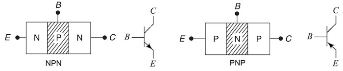
Ans:- A Bipolar Junction Transistor (BJT) is a three-layer, two junction semiconductor device consisting of either two N-type and one P-type layer of material (NPN transistor) or two P-type and one N-type layer of material (PNP transistor). If a thin layer of N-type Silicon is sandwiched between two layers of P-type silicon. This transistor is referred to as PNP. Alternatively, in an NPN transistor, a layer of P-type material is sandwiched between two layers of N-type material.
The term bipolar is to justify the fact that holes and electrons participate in the injection process into the oppositely polarised material. If only one carrier is employed (electron or hole). it is considered a unipolar device.
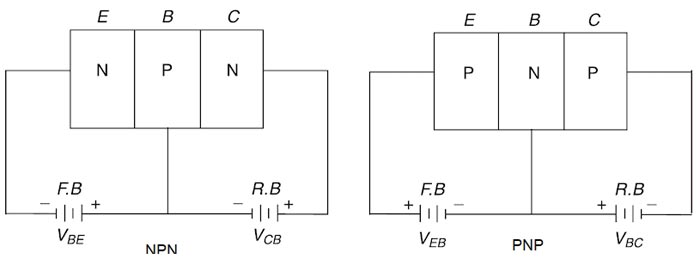
Transistor Biasing
Usually, the emitter-base junction is forward biased and the collector-base junction is reverse biased. Due to the forward bias on the emitter-base junction, an emitter current flows through the base into the collector. Though the, collector-base junction is reverse biased, almost the entire emitter current flows through the collector circuit.
Operation and Current Components of NPN Transistor
The forward bias applied to the emitter-base junction of an NPN transistor causes a lot of electrons from the emitter region to crossover to the base region. As the base is lightly doped with the P-type impurity, the number of holes in the base region is very small and hence the number of electrons that combine with holes in the P-type base region is also very small. Hence a few electrons combine with holes to constitute a base current IB. The remaining electrons (more than 95%) crossover into the collector region to constitute a collector current IC. Thus the base and collector current summed up gives the emitter current, i.e IE = – (IC + IB)
In the external circuit of the NPN bipolar junction transistor, the magnitudes of the emitter current It the base current IB and the collector current IC are related by IE = IC + IB
CIRCUIT CONFIGURATION OF A BIPOLAR JUNCTION TRANSISTOR
A transistor has three terminals: an emitter (E), base (B) and collector (C) and two junctions such as emitter-base junction and collector-base junction. Each of these junctions requires two terminals for a biasing arrangement. When a transistor is connected in a circuit, it requires four terminals, i.e. two input terminals and two output terminals. Therefore, one of the three transistor terminals (emitter, base, and collector) is used as a common terminal between input and output. Depending upon the common terminal, the transistor may be connected to the three different configurations such as common emitter (CE), common base (CB) and common collector (CC) configurations.
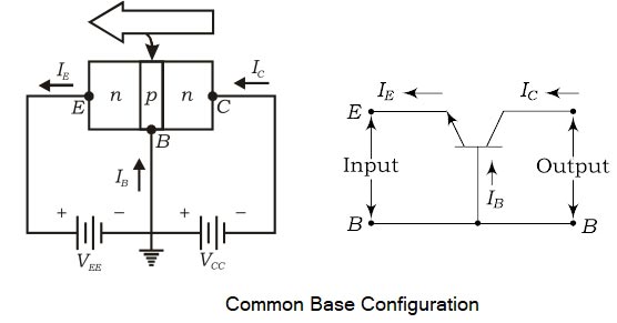
Common-Base Configuration:
In this circuit configuration of a transistor, the base terminal is used as a common terminal between input and output as depicted in Fig. The input signal is applied between the emitter and base terminals. The output will be taken from the collects and base terminals. To explain the operation of NPN and PNP transistors, the common base configuration is used.
Common-Base dc Current Gain
The common-base dc current gain (α) is defined as the ratio of the collector current, Ic, and the emitter current IE and it is represented by α. The dc current gain α can be expressed as
[latex display=”true”]\alpha = \dfrac{{{I_C}}}{{{I_E}}}[/latex]
Since the collector current is always less than the emitter current, the dc current gain α is always less than unity. Usually, the value of α is about 0.98. The dc current can be made closer to unity by controlling the width and doping level of base region as less as possible. Practically, α varies in between 0.95 to 0.998. From the above equation, we get the collector current IC = αIE.
The emitter current is
IE = IB + IC
IE = IB + αIC
as IC = αIE
IB = (1 – α)IE
A common-base configuration offers the following characteristics:
- The transistor circuit will have very low-input impedance
- Very high output impedance
- Unity (or less) current gain
- High-voltage gait and very good high-frequency response and hence find dominant applications in RF amplifiers and high-frequency circuits.
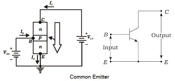
Common Emitter Configuration:
In the common-emitter configuration, the emitter of a transistor is connected to a common terminal between input and output as shown in Fig. The input signal is applied between the emitter and base terminals. The output will be obtained from the collector and emitter terminals. The common emitter configuration of the transistor is the most commonly used one in circuits.
Common Emitter Current Gain β
The current gain, beta (β), is defined for the common-emitter configuration of a BJT and can be defined in two forms: the dc current amplification factor (βdc) and the ac current amplification factor (βac).
The dc current gain βdc is defined as the ratio of collector current to base current at a constant VCE under dc biasing conditions.
[latex display=”true”]{\beta _{dc}} = \dfrac{{{I_C}}}{{{I_B}}}[/latex]
Similarly, the ac current gain, βacis defined as the ratio of change in collector current to a corresponding change in base current at a given VCE under ac signal conditions.
Since the collector current is the output current for a common-emitter configuration and the base current is the input current.
[latex display=”true”]{\beta _{ac}} = \dfrac{{{I_C}}}{{{I_B}}}[/latex]
A common-emitter configuration offers the following characteristics:
- The transistor circuit will have a moderately high input impedance
- Low output impedance
- Moderately high current gain
- Moderately high voltage gain and very good and wide range of frequency response and hence find dominant applications in voltage, current and power amplifiers.
Relation between α and β
[latex display=”true”]\begin{array}{l}{I_E} = {I_B} + {I_c}\\\\\dfrac{{{I_c}}}{\alpha } = \dfrac{{{I_c}}}{\beta } + {I_c}\\\\{\text{Dividing both sides of the equation by }}{I_c}\\\\\dfrac{1}{\alpha } = \dfrac{1}{\beta } + 1\\\\{\text{On Solving}}\\\\\alpha = \dfrac{\beta }{{\beta + 1}}\\or\\\\\beta = \dfrac{\alpha }{{1 – \alpha }}\end{array}[/latex]
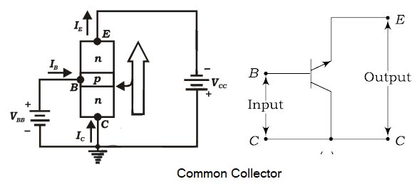
Common-Collector Configuration
In common-collector configuration, the collector terminal of a transistor is connected as common terminal between input and output as shown in fig. The base and collector terminals are used to apply input signal whereas the output signal is obtained. The CC configuration is also commonly known as the emitter follower or the voltage follower. This is because the output signal across the emitter is almost the replica of the input signal with little loss. In other words, the output voltage follows the input voltage and hence the voltage gain will be a maximum of one. The common-collector configuration is used primarily for impedance-matching purposes since it has a high input impedance and low output impedance, opposite to that of the common-base and common- emitter configuration.
Common Collector Current gain- γ
The current gain beta (y) is defined for the common-emitter configuration of a BJT and can be defined in two forms:
The dc current amplification factor (γdc) and the ac current amplification factor (γac).
The dc current gain γdc is defined as the ratio of emitter current to base current under dc biasing conditions.
[latex display=”true”]{\gamma _{dc}} = \dfrac{{{I_E}}}{{{I_B}}}[/latex]
For practical devices, the value of Atypically ranges from about 50 to over 400 (one greater than β)
Similarly, the ac current gain Yac is defined as the ratio of change in emitter current to a corresponding change in base current at a given VCE under ac signal conditions
[latex display=”true”]{\gamma _{ac}} = \dfrac{{{I_E}}}{{{I_B}}}[/latex]
A common-collector configuration offers the following characteristics:
- The transistor circuit will have a very high input impedance,
- Very low output impedance
- Moderately high current gain
- Unity voltage gain and very good and wide range of frequency response and hence find dominant applications in current amplifiers. Because of good impedance-matching properties, this circuit is widely used as driver (buffer) stage in many applications.
[ninja_tables id=27501]
For SSC JE 2017 Electrical paper with complete solution Click Here
For SSC JE 2015 Electrical paper with complete solution Click Here
For SSC JE 2014 (Evening shift) Electrical paper with complete solution Click Here
For SSC JE 2014 (Morning shift) Electrical paper with complete solution Click Here
For SSC JE 2013 Electrical paper with complete solution Click Here
For SSC JE 2012 Electrical paper with complete solution Click Here
For SSC JE 2011 Electrical paper with complete solution Click Here
For SSC JE 2010 Electrical paper with complete solution Click Here
For SSC JE 2009 Electrical paper with complete solution Click Here