
Ques.41. Which of the following automatic welding process is likely to give the maximum rate of metal deposition?
- Gas shielded bare wire
- Submerged arc (single wire)
- Multiple power submerged arc
- Continuous flux covered electrode
Answer.3. Multiple power submerged arc Explanation:- Submerged arc welding (SAW). An arc welding process that uses an arc or arcs between a bare metal electrode or electrodes and the weld pool. The arc and molten metal are shielded by a blanket of granular flux on the workpieces. The process is used without pressure and with filler metal from the electrode and sometimes from a supplemental source (welding rod, flux, or metal granules). Deposition welding is a generating process that is applied for surface finishing as well as repairing or modifying existing components. Depending on the task at hand, either manual or automated laser deposition welding is used. In twin Submerged arc welding (SAW), two electrodes are used simultaneously instead of one. Hence, weld deposit size is increased considerably. Moreover, due to an increase in welding current (upto 1500 A), much deeper penetration of the base metal is achieved.
Ques.42. The load taken by a welding transformer is
- Purely resistive
- Non-inductive
- Highly-Inductive
- Highly- Capacitive
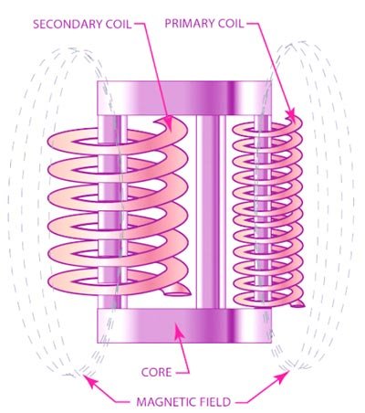
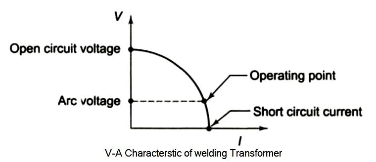
Answer.3. Highly-Inductive Explanation:- An AC welding set is nothing but a transformer. A DC rectifier welding set also comprises essentially of a transformer and a rectifier unit. In both cases, the transformer has to perform the two essential functions. The first function is the normal function of a transformer. The second requirement it fulfills either by providing a high leakage reactance in its windings (i.e., reducing coupling factor between windings) or bar connecting a reactor in series with the secondary. The arc striking voltage is normally between 70 to 100 V in the case of AC and 50 to 80 V in the case of DC welding for different types of jobs. For welding work in narrow combined spaces such as tanks the no-load voltage specified may be still lower. Before the arc is formed i.e. before the air between the electrode and the job is ionized, there is infinite resistance in the secondary circuit, no current flows, no drop in the leakage reactances or in the series reactor, so the full secondary emf induced appears, as the striking voltage between the electrode and the job. Once the arc is struck, the passage of air between the electrode and the job is ionized the resistance suddenly falls to the very low value and has −VE characteristics i.e., resistance goes on falling with increasing arc current. So the voltage across the arc must be reduced to some value which will stabilize the arc current. This running arc voltage is around 25 to 30 volts in the case of AC and 20 to 25 volts in the case of DC welding jobs. The high leakage reactance means the short-circuit impedance, Zsc, is large and so the short-circuit current is much smaller than in a conventional design. This is necessary with arc-welding transformers because the arc must be struck with a relatively high secondary voltage, but when struck the secondary load has low resistance and the voltage must be considerably reduced. Therefore the welding transformer is highly inductive in nature and the power factor of the welding transformer is 0.3 to 0.5 laggingWelding Transformers
Ques.43. The power factor of the load using the welding transformer is usually
- Unity
- Nearly unity lagging
- Nealy unity leading
- Very low of the order of 0.3 to 0.5 lagging
Answer.4. Very low of the order of 0.3 to 0.5 lagging Explanation:- Arc welding transformer is also designed to have a high leakage reactance so as to stabilize the arc during the welding process. The open-circuit voltage is about 70 V, which facilitates striking the arc when the electrode touches the world, However, as soon as the arc is established tile secondary voltage falls to about I5 V, a value that depends upon the length of the arc and the intensity of the welding current. Due to the high leakage reactance power factor of welding transformer is 0.3 to 0.5 lagging
Ques.44. Bare type electrodes are
- Consumable
- Non-consumable
- Any of the above
- None of the above
Answer.1. Consumable Explanation:- Bare electrode These are the consumable electrodes, which are not coated with any fluxing material. Bare electrodes are in the form of a wire. During the welding operation, an arc is struck between the workpiece and the electrode wire, then the electrode is melted down into the weld. When the molten metal electrode and the workpiece are exposed to the atmosphere of oxygen and nitrogen, they form their oxides and nitrides and cause the formation of some non-metallic constituent, which reduces the strength and ductility of the deposited weld. The bare electrodes are usually employed in automatic and semiautomatic welding. With a bare electrode, the welding can be done satisfactorily with DC supply only if the electrode should be connected to the negative terminal of the supply.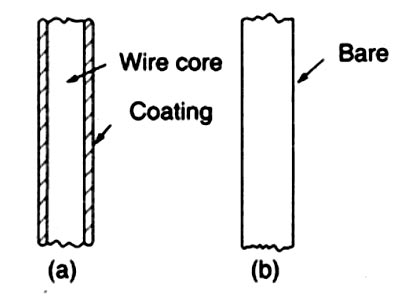
Ques.45. For power factor correction of welding transformer, a capacitor is usually connected on
- Primary side
- Secondary side
- Parallel to arcing electrodes
- Parallel to mains
Answer.1. Primary side Explanation:- Because the load taken by a welding transformer is highly inductive, the power factor will necessarily be low. For single-operator equipment it is of the order of 0.3- 0.5 lagging, depending on the design of the set and the type of electrode used, arc length, etc. It is well known that the greater the inductance of the welding circuit, the better the conditions. A welding set that is not provided with a capacitor or other means of power factor correction cannot operate at a high power factor. The simple, single-phase transformer welding source lends itself readily to power-factor correction by the connection of a capacitor on the primary side. Power sources are available in which the capacitor is incorporated in or attached to the welding transformer. If the capacitor is connected in parallel, it would be energized all the time the isolator is closed and a heavy leading current would flow when the machine was not actually welding The output of capacitors for single and two-phase welding transformers and resistance welding machines needs to be up to 50% of the nominal transformer capacity. For welding rectifiers, a capacitor output of about 10% of the nominal capacity of the transformer/rectifier is sufficient. Three-phase welding machines can be provided capacitors with around 33% of their KVA rating. It is standard practice to switch the capacitors on and off with the welding transformer to avoid loading the supply with the capacitive current when not necessary. A specially designed current sensing relay and a fast discharging arrangement for the capacitor are deployed to adjust to the welding process at a fast rate. The capacitor used for the power factor is specially provided with an arrangement for quick discharge so that it can be switched on again in a short time. This allows the controller to follow the welding cycle properly. Where many single-operator sets are connected, care must be taken not to overcorrect the power factor. It must be kept in mind that a welding load is intermittent, and probably for 50% of the time for which the set is connected no welding will be in progress. If therefore, each welding equipment is provided with a separate capacitor, there is the danger of a leading load being taken if the diversity factor of the welding load is small. This difficulty may be overcome by:Power-factor correction
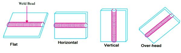
Ques.46. The Position of arc welding is
- Flat position
- Horizontal position
- Vertical Position
- All of the above
Answer.4. All of the above Explanation:- There are four basic positions in which manual arc welding is done.
Ques.47. MIG welding is
- Mild steel inert gas welding
- Medium inert gas welding
- Maximum inner depth gas welding
- Metal inert gas welding
Answer.4. Metal inert gas welding Explanation:- Gas metal arc welding (GMAW) also called MIG (metal inert gas) if the shielding gas is inert, for example, argon, or MAG (metal active gas) if the gas has a content of an active gas such as CO2. In Europe, the process is usually called MIG/MAG or just MIG welding. The process is used in a wide range of plate thicknesses even though it has been most dominant in thin sheet welding. This is because of its easiness in starting and stopping and thereby its relatively high productivity. Compared to stick electrode (MMA) welding there is no need for frequent electrode changes and slag removal. The principle of MIG welding is that a metallic wire is fed through the welding gun and melted in an arc. The wire serves the dual purpose of acting as the current-carrying electrode and as the weld metal filler wire. Electrical energy for the arc is supplied by a welding power source. The arc and the pool of molten material are protected by a shielding gas, which is either inert or active. In this context, an inert gas is one that does not react with the molten material. Examples of gases in this category are argon and helium. Active gases, on the other hand, participate in the processes in the arc and the molten material. Argon containing a small proportion of carbon dioxide or oxygen is an example of an active gas. In order to achieve optimum welding performance, it is important that the welding parameters are set correctly. Examples of such parameters in MIG welding are voltage, wire feed speed, and shielding gas flow.
Ques.48. The advantage of resistance welding are
- Less skill required
- Reduced distortion
- No need for filler material
- All of the above
Answer.4. All of the above Explanation:- In the resistance welding (RW) process the weld is made by clamping the parts together between the welding machine’s electrodes. Then an electric current is passed through the parts to heat up the surfaces so they will fuse together. Advantages of resistance welding Disadvantages of resistance welding Applications of resistance welding
Ques.49. Which of the following is not resistance welding?
- Projection welding
- MIG welding
- Seam welding
- Flash butt welding
Answer.2. MIG welding Explanation:- Types of resistance welding Depending upon the method of weld obtained and the type of electrodes used, the resistance welding is classified as: 1. Spot welding. 2. Seam Welding. 3. Projection welding. 4. Butt welding. Note:- MIG welding is a gas welding process
Ques.50. When t is the thickness of the sheet, the tip diameter for spot welding is usually
- 2t
- t
- √t
- 1/t
Answer.3. √t
Explanation:-
The diameter of the spot weld decreases as the diameter of the electrode tip increases. Also, if the electrode tip is too small, the spot weld will not increase in size. The tip diameter must be properly controlled to obtain the desired welding strength. Before starting opera lion, make sure that the tip diameter (D) is kept the proper size, and file it cleanly to remove burnt or foreign matter from the surface of the tip. As the amount of dirt on the tip increases, the resistance at the tip also increases, which reduces the current flow through the base metal, which in turn reduces weld penetration resulting in an inferior weld.
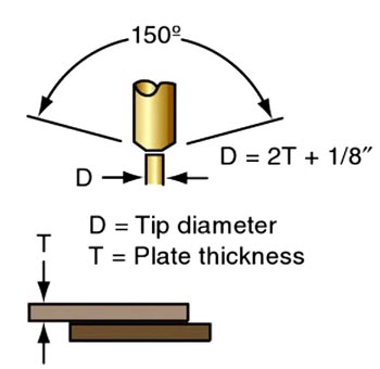
Use the formula to determine the tip diameter two times the plate thickness plus 1/8 inch or 3.2 mm. Usually, the tip diameter is made approximately equal to the square root of the sheet thickness.
D = 2T + 1/8″
or D = √T
Where
T = thickness of the sheet
