In the synchronous motor, the stator and rotor rotate at the same speed.
Ques.72. Which of the following lamps employs a bimetallic strip?
Fluorescent lamp
Mercury vapor lamp
Incandescent lamp
Sodium vapor lamp
Answer.1. Fluorescent lamp
Explanation:-
A fluorescent lamp is a hot cathode low-pressure mercury-vapor lamp.
Construction of Fluorescent lamp
It is a low-pressure mercury-vapor lamp. Due to low pressure, the lamp is in the form of a long tube, coated inside with phosphor.
The tube contains a small amount of mercury and a small quantity of argon gas at a pressure of 2.5 mm of mercury.
At each end of the tube, the electrodes are of spiral form made of tungsten and coated with an electron-emitting material.
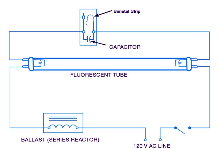
A choke is connected in series with the tube filament. ft provides a voltage impulse for starting the lamp and acts as a ballast later on when the lamp is running.
The filament is connected to a starter switch which is a small cathode glow lamp with a bimetal strip at the electrodes.
Working of Fluorescent lamp
At the time of starting, when both the lamp and the glow starters are cold, the mercury is in the form of globules.
When supply is switched on, the glow starter terminals are open-circuited and full supply voltage appeared across these terminals, due to the low resistance of electrodes and choke coil.
The small quantity of argon gas gets ionized, which establishes an arc with a starting glow.
This glow warms up the bimetallic strip, and the strip gets bend thus glow starts gets short-circuited. Hence, the two electrodes come in series and are connected across the supply voltage.
Now, the two electrodes get heated and start emitting electrons due to the flow of current through them. These electrons collide with the argon atoms present in the long tube discharge that takes place through the argon gas.
So, in the beginning, the lamp starts conduction with argon gas as the temperature increases, the mercury changes into vapor form and takes over the conduction of current.
Ques.73. Let T be the net torque developed by the rotor runs at ω rad/s. What is the mechanical power developed?
Pmech = (2πωT)/60
Pmech = (ωT)/60
Pmech = ωT
Pmech = (2πωT)
Answer.3. pmech = ωT
Explanation:-
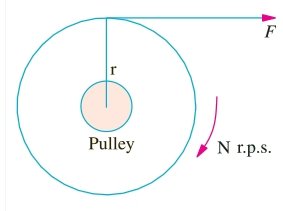
By the term, torque is meant the turning or twisting moment of a force about an axis. It is measured by the product of the force and the radius at which this force acts. Consider a pulley of radius r meter acted upon by a circumferential force of F Newton which causes it to rotate at N r.p.m.
The angular speed of the pulley is
ω = 2πN/60 rad/sec
Work is done by this force in one revolution
= Force × distance = F × 2πR Joule
The power developed = Work Done/Time
= (F × 2πR)/60/N
= (F × R) × (2πN)/60
The power developed = T × ω watt or P = T ω Watt
pmech = (ωT)
Ques.74. If an alternator is operating at unity power factor, then its terminal voltage is
Equal to the induced EMF, with zero voltage regulation
Less than the induced EMF, with negative regulation
Less than the induced EMF, with positive voltage regulation
Greater than the induced EMF, with negative voltage regulation
Answer.3. Less than the induced EMF, with positive voltage regulation
Explanation:-
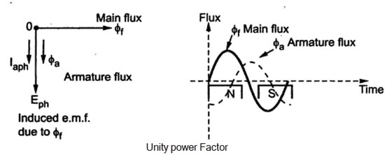
Unity Power Factor Load (Cross-Magnetizing)
Consider a purely resistive load connected to the alternator, having a unity power factor. As induced e.m.f Eph drives a current Iph and load power factor is unity, Ephand Iph is in phase with each other.
If φf is the main flux produced by the field winding responsible for producing Ephthen Eph lags φf by 90°.
Now current through armature Ia produces the armature flux say to,, So flux φa, and la are always in the same direction.
It can be seen from the phasor diagram that there exists a phase difference of 90°between the armature flux and the main flux. From the waveforms, it can be seen that the two fluxes oppose each other on the left half of each pole while assisting each other on the right half of each pole. Hence average flux in the air gap remains constant but its distribution gets distorted. Hence such distorting effect of armature reaction under unity p.f. the condition of the load is called the cross magnetizing effect of armature reaction. Due to such distortion of the flux, there is a small drop in the terminal voltage of the alternator
Voltage Regulation:-
The difference in voltage at the receiving end of a transmission line between conditions of no-load and full-load is called voltage regulation and is expressed as a percentage of the receiving end voltage. Mathematically,
% Voltage regulation = (Vs − VR) ⁄ VR × 100
The value of the regulation not only depends on the load current but also on the power factor of the load.
For lagging and unity p.f. conditions there is always a drop in the terminal voltage hence regulation values are always positive.
While for leading capacitive load conditions, the terminal voltage increases as load current increases. Hence the regulation is negative in such cases.
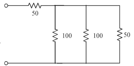
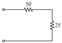
Ques.75. In the circuit shown, find the equivalent resistance between A and B.
75 ohm
100 ohm
150 ohm
50 ohm
Answer.1. 75 ohm
Explanation:-
The resistance R3 & R4 are connected in series
= (30 + 70) = 100Ω
Now three resistor i.e 100Ω, 100Ω & 50Ω is connected in parallel
1/Rp = 1/100 + 1/100 + 1/50
Rp = 100/4 = 25 Ω
Resistance 50Ω and 25Ω are connected in series.
Rtotal = (50 + 25)Ω
Rtotal = 75Ω
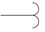
Ques.76. The below symbol which is used in single line diagrams represents
Potential transformer
Power transformer
Current transformer
Circuit breaker
Answer.1. Potential transformer
Explanation:-
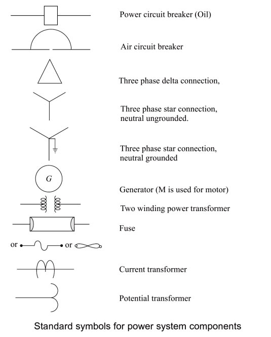
The single-line diagram (also called one-line diagram) is a pictorial representation of connections of various components of the power system, using standard symbols for components and lines for the transmission lines connecting them.
The symbol given in the question is of Potential transformer.
Ques.77. P = ρQHg is the water power equation. Head ‘H’ is measured in meter ‘g’ gravity constant is measured in meter/second square, then the measuring unit of ‘Q’, the flow rate of water is:
Meter per hour
Square meter per second
Meter per second
Cubic meter per second
Answer.4. Cubic meter per second
Explanation
P = ρ QHg is the water power equation.
Where
H = heead = meter
g = gravity =m/s2
ρ =density = (kg/m3)
P = power = watt = N-m/sec
Q = water flow rate = m3/sec
Ques.78. In a capacitor start single phase induction motor the current in the:
The main winding leads the voltage
Supply lines lead the voltage
Starting winding leads the voltage
Starting winding lags the voltage
Answer.4. Starting winding leads the voltage
Explanation
In the capacitor start, single-phase induction motor the capacitor is connected in series with the starting auxiliary winding. In this manner, the current in the starting winding may be made to lead the line voltage. Since the running winding current lags the line voltage, the phase displacement between the two currents is made to approximately 90° on starting.
Placing the capacitor in the auxiliary winding circuit to produce a greater phase difference between the current in the main and the auxiliary windings. Due to greater phase difference capacitor Start motors have very high starting torque for a single-phase AC motor.
Ques.79. An electric heater is connected across 230V and it draws a current of 2A. Then the resistance offered by the heater is?
115 ohm
29 ohm
290 ohm
11.5 ohm
Answer.1. 115 ohm
Explanation
Given
Voltage V = 230 V
Current I = 2 A
Resistance R = V/I
R = 230/2 = 115 Ω
Ques.80. A coil is wound with 50 turns and a current 8A produces a flux of 200μWb. Calculate the inductance of the coil.
0.125 mH
1.25 mH
0.25 mH
2.5 mH
Answer.2. 1.25 mH
Explanation
The inductance of the coil is given by the relation