
Ques 2(a). Define the following terms
- Magnetic Field Intensity
- Magnetic Flux Density
- Magnetomotive Force
- Reluctance
Answer:-
(A) MAGNETIC FIELD INTENSITY
Magnetic field Intensity (H) is also called as Magnetic field Strength, Magnetic Intensity, Magnetic field, Magnetic Force and Magnetization Force.
Magnetic Field Strength (H) gives the quantitative measure of strongness or weakness of the magnetic field.
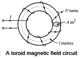
Suppose that a current of I amperes flows through a coil of N turns wound on a toroid of length I meters. The mmf is the total current linked to the magnetic circuit i.e IN ampere-turns. If the magnetic circuit is homogeneous and of the uniform cross-sectional area, the mmf per meter length of the magnetic circuit is termed as the magneticfield strength, magnetic field intensity, or magnetizing force. It is represented by symbol H and is measured in ampere-turns per meter (At/m).
[latex display=”true”]H = \dfrac{\mathbb{F}}{L} = \frac{{IN}}{l}[/latex]
Hence the magnetic field Intensity can be defined as the ratio of applied MMF to the length of the path that it acts over.
Note:- Magnetic field intensity, H, is independent of the medium. Its value depends only on the number of turns N and the current I flowing in the coil.
Magnetic Field Strength is equivalent to Voltage gradient in an Electrical Circuit.
(B) MAGNETIC FLUX DENSITY
The strength of the magnetic field is measured by the number of magnetic lines of flux there are in a given cross-sectional area; the more lines of magnetic flux, the stronger the magnetic field. The greater the magnetic flux density, the more lines of magnetic flux are available to cut through the electrical conductor(s) for a given speed of cutting action, and the greater will be the induced voltage.
The Number of Magnetic lines of force emerging through an imaginary surface in a magnetic field is called as the Magnetic Flux (Φ) of the Field. Its Unit of measurement is Weber.
Magnetic flux density (B) is defined as the magnetic flux per unit area of a surface at the right angle to the magnetic field. This is also known as magnetic induction. Its symbol is B and measured in Weber per square-meter or Tesla.
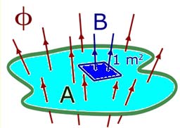
Φ = B.A(wb)
B = Φ/A (Tesla)
Where Φ = magnetic field
B = Flux density
A = Surface area
Relation Between Magnetic Flux Density and Field Intensity
At any point in a magnetic field, field strength or field intensity H is the force maintaining the magnetic flux and producing a particular value of flux density B at that point. Hence the field intensity H is the cause and the flux density B the effect. Thus the flux density can be assumed proportional to field intensity in the magnetic field i.e. in free space,
B=μoH
(C) MAGNETOMOTIVE FORCE
The term magnetomotive force was discovered by Henry Augustus Rowland in 1880.
Magnetomotive force (symbol: F), which is often abbreviated to m.m.f., is the term used to describe the means by which magnetic flux is set up within a magnetic circuit. In all practical magnetic circuits, this is provided using a current-carrying winding (coil) and is the product of the current and the number of turns in the winding. Its Sl unit of measurement is the ampere-turn and their CGS unit is G (Gilbert).
OR
Current through a coil creates magnetic flux. The greater the current or the greater the number of tums, the greater will be the flux. This flux-producing ability of a coil is called its magnetomotive force (mmf).
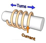
F = Nl (ampere-turns, At)
Where
F = m.m.f in ampere
I = Current in ampere
N = Number of turns(no unit)
Thus, a coil with 100 turns and 2.5 amps will have an mmf of 250 ampere-turns, while a coil with 500 turns and 4 amps will have an mmf of 2000 ampere-turns.
Magnetomotive force is similar to electromagnetic force in terms of an electric circuit.
Note:- Since the m.m.f is the product of amper and a simple number (of turns), its Sl unit of measurement is the ampere’ but, to avoid confusion with the unit for current, it is usually spoken or pronounced as ‘ampere-turn:
Despise its unit of measurement, it’s important to realize that m.m.f is equivalent to e.m.f and not current.
(D) RELUCTANCE
Flux in a magnetic circuit also depends on the opposition that the circuit presents to it. Reluctance (RM), is the opposition a magnetic circuit offers to the formation of magnetic flux.
The opposition depends on the dimensions of the core and the material of which it is made. Like the resistance of a wire, reluctance is directly proportional to length (L) and inversely proportional to cross-sectional area (A). In equation form,
RM = L/A (Ampere-Weber)
The unit of Reluctance is Ampere-Weber or A/Wb
To change the ‘proportional’ sign into an ‘equals’ sign we must introduce a constant. This constant is called ‘magnetic reluctivity‘ and is directly equivalent to ‘resistivity’ in an electric circuit. However, it’s far more common to use its reciprocal instead, which we call ‘absolute permeability(μ)‘ Which is equivalent to conductivity.
Permeability is a measure of how easy it is to establish the flux in a material. Ferromagnetic materials have high permeability and hence low RM, while nonmagnetic materials have low permeability and high RM.
RM = L/μA
Ques 2(b). In a pair of coupled coils, coil 1 has a continuous current of 2A and the corresponding fluxes Φ11 and Φ12 are 0.6 and 0.3 mWb respectively. If the turns are N1 = 500 and N2 = 500. Find L1, L2, M, and K.
Answer:- For cofficient of mutual coupling derivation visit SSC JE Conventional Paper 2016 Question Number 2.
Given
Φ11 = 0.6
Φ12 = 0.3
N1 = N2 = 500
Current I11 = 2A
(i) Self-Inductance of coil L1
Self-Inductance of coil L1 = N1Φ11/I11 = 500 × 0.6 × 10-3/2
L1 = 0.15 H
Now Mutual Inductance M
M = N1Φ11/I11 = N2Φ12/I12 =
0.15 = 500 × 0.3 × 10-3/I12
I12 = 1 A
(ii) Self Inductance of coil L2
L2 = N2Φ12/I12 = 500 × 0.3 × 10-3/1
L2 = 0.15 H
(iii) Coefficient of coupling K
The coefficient of coupling K = Φ1/Φ12
= 0.3/0.6 = 0.5
(iv) Mutual Inductance M
Mutual Inductance M is given as
[latex]\begin{array}{l}M = K\sqrt {{L_1}{L_2}} \\\\M = 0.5\sqrt {0.15 \times 0.15} \\\\M = 0.075H\end{array}[/latex]
Ques 2(c). An AC voltage of 50 Hz has a maximum value of 50 V. What will be its voltage after 1/600 second.
Answer:-.
Given
Maximum voltage Vm = 50 V
Frequency = 50 Hz
Time = 1/600 sec
The instantaneous equation of the voltage is given as
V = Vm sinωt
Where ω = angular frequency = 2πf
V = Vm sin2πf t
= 50 sin2π × 50 × t
= 50 sin100πt
At t = 1/600 sec.
V = 50 sin100π × 1/600
= 50 sin (100 × π°)/600
= 50 sin(π/6)
= 50/2…………..(since sinπ/6 = sin30° = 1/2)
= 25 V
Ques 2 (d):- A circuit with a resistor, inductor, and capacitor in series is resonant of fo Hz. If all the component values are now doubled, find the new resonant frequency.
Answer:-
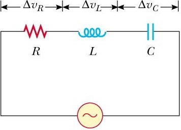
In RLC series circuit the total impedance of the series LCR circuit is given as
Z2 = R2 + (XL – XC)2
where XL is inductive reactance
and XC is capacitive reactance.
At a particular frequency (resonant frequency), we find that XL= XC because resonance of a series RLC circuit occurs when the inductive and capacitive reactances are equal in magnitude but cancel each other because they are 180 degrees apart in phase. Therefore, the phase angle between voltage and current is zero and the power factor is unity.The point at which this occurs is called the Resonant Frequency point, ( ƒo ) of the circuit.
Now Inductive reactance XL = 2πfL = ωL …………(since angular frequency ω = 2πf)
Capacitive Reactance XC = 1/2πfC = 1/ωC
As we Know that in series Resonance Circuit XL= XC therefore
[latex]\begin{array}{l}2\pi {f_o}L = \dfrac{1}{{2\pi {f_o}C}}\\\\{f_o} = \dfrac{1}{{4{\pi ^2}LC}}\\\\{f_o} = \dfrac{1}{{2\pi \sqrt {LC} }}\end{array}[/latex]
Now the value of all the component is doubled i.e
R becomes 2R
XL become 2XL
XC becomes 2XC
Then the new Resonant frequency will be
[latex]\begin{array}{l}{f_{new}} = \dfrac{1}{{2\pi \sqrt {4LC} }}\\\\{f_{new}} = \dfrac{1}{{4\pi \sqrt {LC} }}\\\\{f_{new}} = \dfrac{{{f_o}}}{2}\end{array}[/latex]