Ques.31. The stepped core is used in transformers in order to reduce (SSC 2014)
Volume of Iron
Volume of copper
Iron loss
Reluctance of core
Answer.2.Volume of Copper
Explanation:-
For medium and large capacity transformer circular coils are used because they are mechanically stronger.
It is more economical to use circular shape coils around the stepped core. For the same area of the iron core, required by magnetic flux the diameter of the circumscribing circle (d) gets reduced with an increase in the number of steps.
The reduction of diameter “d” will reduce the mean length turn of the winding around the core. Thus lesser copper (mean turn wise) will be used and the cost will reduce.
The core area also can be better utilized for cooling purposes and mechanically the core structure will be stable with stackings intact.
Ques.32. The transformer used in a welding set is (SSC 2014)
Step-up transformer
Step-down transformer
Constant Current transformer
Booster transformer
Answer.2.Step-down Transformer
Explanation:-
A welding power supply is a device that provides an electric current to perform welding. Welding usually requires high current (over 80 amperes) and it can need above 12,000 amperes in spot welding.
Welding transformer is a step down electrical transformer that converts the moderate voltage and moderate current electricity from the utility mains (typically 230 or 115 VAC) into a high current and low voltage supply, typically between 17 and 45 (open-circuit) volts and 55 to 590 amperes.
Ques.33. The primary and secondary windings of a transformer are wound on the top of each other in order to reduce ___ (SSC 2015)
Iron losses
Leakage reactance
Copper losses
Winding Resistance
Answer.2.Leakage Reactance
Explanation:-
A secondary coil is wound over the primary coil in a transformer to have maximum flux linkages such that the maximum efficiency is obtained. By doing this, the distance between the coils is reduced and thus lower flux leakages.
Ques.34. Leakage flux in a transformer occurs because (SSC 2015)
The applied voltage is sinusoidal
Air is not a good magnetic insulator
The transformer is not an efficient device
Iron core has high permeability
Answer.2. Air is not a good magnetic insulator
Explanation:-
Leakage Flux
The flux that does not pass through the air gap or useful part of the magnetic circuit is called as leakage flux since air is the bad magnetic insulator, therefore, it is a common phenomenon in the transformer.
Ques.35. The no-load input power to a transformer is practically equal to ______ loss in the transformer (SSC 2015)
Windage
Eddy current
Copper
Iron
Answer.4. Iron
Explanation:-
At no load practical transformer, primary copper loss I02R is very small and this loss may be neglected. Hence, the primary no-load input power of practical transformer is equal to the iron loss.
No-load input power, W0 = Iron loss
Ques.36. The error in the current transformer can be reduced by designing them with (SSC 2015)
Using large cross-section for both primary and secondary windings conductors
High permeability and low core materials, avoiding any joints in the core and also keeping the flux density to a low value
Using primary and secondary winding as close to each other as possible
All of the above
Answer.4. All of the above
Explanation:-
The error in the current transformer can be reduced by the following methods
Using the core of high permeability and low hysteresis loss magnetic materials.
Lowering the secondary internal impedance.
Ensuring the minimum length of the flux path and increasing the cross-sectional area of the core, minimizing joint of the core.
Keeping the rated burden to the nearer value of the actual burden.
Ques.37. The no-load primary current Io is about ________ of full load primary current of a transformer (SSC 2015)
3-5%
above 40%
15-30%
30-40%
Answer.1. 3-5%
Explanation:-
A transformer is said to be on “no-load” when its secondary side winding is open-circuited. When the transformer is in no-load condition there will be no current in the secondary section. The losses on the primary side are the core loss, dielectric loss and copper loss due to excitation current are the no-load losses and usually, they are pretty small which is about 2 – 5% of full load.
Ques.38. What is the efficiency of the transformer compared with that of the electrical motors of the same power? (SSC 2016)
Very less
Much Higher
Less
Equal
Answer.2. Much Higher
Explanation:-
As the Transformer is a static device, it does not have any rotating parts hence the mechanical losses are absent which increases the efficiency of the transformer. Transformer efficiency is generally greater than 90 – 95%, while that of the motors is about 70 to 75%.
Ques.39. For a 100% efficient transformer, the primary winding has 1000 turns and the secondary 100 turns. If the power input to the above transformer is 1000 watts, the power output is (SSC 2016)
100 Watts
10 Watts
1 Watt
1000 Watts
Answer.4. 1000 Watts
Explanation:-
If a transformer is 100% efficient then
Power supply to the primary = Power supply to the secondary.
Power supply to primary = 1000 Watt (given)
Therefore the power supply to the secondary = 1000 watt
Ques.40.A no-load test is performed on a transformer to determine (SSC 2016)
Magnetizing current only
Core losses only
Efficiency
Magnetizing current and losses
Answer.4. Magnetizing current and losses
Explanation:-
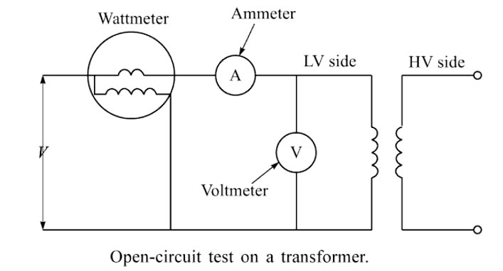
An open circuit test is also called a no-load test. The open-circuit test on a transformer is generally made on the low-voltage side as shown in Figure. It means that all the instruments are connected on the low-voltage side and a lower-rated voltmeter can be used. There is no problem with the ammeter because the open-circuit current of the transformer is already low. The high-voltage side is kept open. In the transformer, the Magnetizing current and core losses depend on the applied voltage and are practically unchanged by the load current. Therefore, to achieve these parameters, the rated voltage is applied to one of the winding.
The fundamental principle of this test is that normal rated voltage is applied to one winding while the other is left the open circuit. The current flowing in the winding to which the supply is connected is the magnetizing current and this is recorded as part of the test records. Under OC conditions the transformer LV draws only magnetizing current, which is very small compared to the full load current so I2R loss is negligible compared with the core loss. To avoid unnecessarily high voltages in the test circuit during the core loss test, it is normal practice to connect the supply to the lower voltage winding of the transformer.