Ques 41. Perfect reproducibility means the instrument has
Zero Drift✔
High accuracy
Maximum drift
Minimum accuracy
For an instrument, perfect reproducibility means that the instrument has no drift. This means that for a given input, the measured values are constant and do not vary with time.
Ques 42. Transducers maybe not be called as
Gauges
Pickups
Signal generators
Amplifier✔
A device that converts a physical quantity into a proportional electrical signal is called a transducer.
The electrical signal produced may be a voltage, current, or frequency. A transducer uses many effects to produce such conversion. The process of transforming the signal from one form to other is called transduction.
A transducer is also called pick up. For example, a thermocouple converts the heat energy into electrical energy, a microphone converts the sound energy into electrical energy, a strain gauge converts pressure, and force-like mechanical energy into electrical energy.
Whereas, An amplifier, electronic amplifier, or (informally) amp is an electronic device that can increase the power of a signal (a time-varying voltage or current). An amplifier uses electric power from a power supply to increase the amplitude of a signal. So the transducer is not an amplifier.
Ques 43. Current passing through an inductor is 4 A. Energy stored in the inductor of inductance 0.2 Henry will be
The loudness of sound is measured in units called decibels (dB). A decibel unit expresses the relative intensity of sounds on a scale from zero for the average least perceptible sound to about 100 dB, which is near the level most people find uncomfortably loud.
Ques 45. At much lower temperatures semiconductors behave as
Semiconductors only
Conductors
Insulators✔
Conductor or insulator
The resistance of semiconductor, Insulator, and Electrolyte(silicon, Glass, Varnish, etc) decrease with an increase in temperature. At zero temperature or very low temperature, the semiconductor behaves as a perfect insulator.
As the temperature increases, some of the electrons acquire energy and become free for conduction. Hence, conductivity increase and resistance decrease with an increase in temperature.
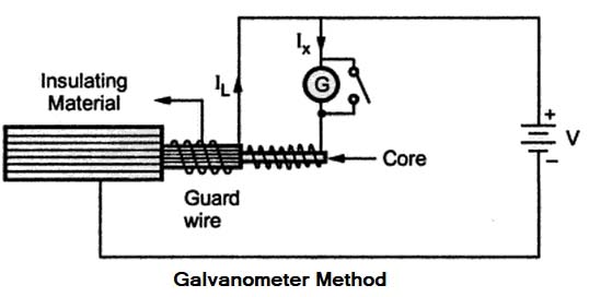
In this method, a high resistance (more than 1000 Q.) and very sensitive moving coil galvanometer is connected in series with the resistance to be measured along with supply voltage. By this method, insulation resistance can be obtained with respect to the deflection of the galvanometer.
Megger
Megger is based on the principle of Electromagnetic Induction. When a current-carrying conductor is placed in a uniform magnetic field it experiences mechanical force whose magnitude depends upon the strength o the current and magnetic field. While its direction depends on the direction of the current and magnetic field.
Construction of Megger
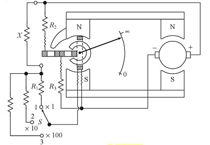
It consists of a permanent magnet that provides the field for both the generator G and ohmmeter. One of the moving coils is called the current coil. There are two coils rigidly fixed perpendicular to the current coil and are called voltage coils. The outer voltage coil is called a control coil while the inner voltage coil is called a compensating coil. These coils are mounted on the central shaft which is free to rotate over a stationary C-shaped iron core.
The control coil moves over the annular core while the compensating coil moves over the extension of the pole piece of the permanent magnet. The torque produced by the current coil opposes the torque produced by the voltage coils. The current coil is in series with a resistance R1 and the unknown resistance X is connected across the supply. Thus the current through the current coil is the same as that through the unknown resistance X. The two voltage coils in series are connected, in series with resistances R2 and R3, across the supply. Thus, the current through the voltage coils is proportional to the volt drop across the current coil.
Working of Megger
When the current flows from the generator, through the pressure coil the coil tends to set itself at right angles to the field of the permanent magnet.
When the test terminals are open, corresponding to infinite resistance, no current flows through the deflection coil. Thus the pressure coil governs the motion of the moving element making it move to its extreme anticlockwise position. The pointer comes to rest at the infinity end of the scale.
When the test terminals are short-circuited i.e. corresponding to zero resistance, the current from the generator flowing through the current coil is large enough to produce sufficient torque to overcome the counter-clockwise torque of the pressure coil. due to this, the pointer moves over a scale showing zero resistance.
When the high resistance to be tested is connected between terminals T1 and T2the opposing torques of the coils balance each other so that pointer attains a stationary position at some intermediate point on the scale. The scale is calibrated in megaohms so that the resistance is directly indicated by the pointer.
Ques 48. If there are no copper losses in the rotor, then
Hence if there are no copper losses in the rotor, then rotor output will become equal to rotor input and the rotor will run at synchronous speed.
Ques 49. Type(s) of DC drives is/are:-
Regenerative
Non -generative
Single-phase
All of the above✔
An electrical drive is an industrial system that performs the conversion of electrical energy into mechanical energy or vice versa for running and controlling various processes. Very low power drives are generally fed from single-phase sources. The rest of the drives are powered by a three-phase source.
DC Drive is classified into two types:
Non-regenerative DC drives: Non-regenerative DC drives are the most conventional type. In their most basic form, they are able to control motor speed and torque in one direction.
Regenerative DC drives: Regenerative adjustable speed drives, also known as four-quadrant drives, are capable of controlling not only the speed and direction of motor rotation but also the direction of motor torque.
Ques 50. Pollution due to Tidal Energy generation is usually
Zero✔
Low
Moderate
High
Tidal energy is the environmentally friendly and clean form of energy which means it is free of carbon emission and pollution hence Pollution due to tidal Energy generation is zero.