Ques.31. The relation VL = √3Vph in a three-phase system is applicable to
Six-phase system load
Delta-connected load
Star-connected load without a neutral point
Star connected load✓
In star-connected load, the phase voltage between the neutral point and any one of the line connections is 1/√3 × VL of the line voltage.
Therefore the line voltage is √3 times the phase voltage.
i.e VL = √3Vph
Note:- In star connection the line current is equal to the phase current.
Ques.32. Find the line current if a three-phase star-connected system is connected to a 400 V, 50 Hz AC supply. Assume Zph = (9.8 + j10)Ω
28.57 A
16.5 A✓
10 A
11.44A
Given
Voltage = 400 V
Zph = (9.8 + j10)
|Zph| = (9.82 + 102)1/2
|Zph| = 14Ω
also
VP = VL/√3 = 400/√3
VP = 230V
IP = Vp/Zp
IP = 230/14
IP = 16.5A
In star connection, the line voltage is equal to the phase voltage
IP = IL = 16.5A
Ques.33. What will be the total power consumed when three coils, each having a resistance of 10 ohms and an impedance of 0.02 H, are connected in star across a 440-V, 50 Hz, three phase
13.1 kW✓
25 kW
21.51 kW
10 kW
Given
Inductance L = 0.02 H
Resistance R = 10 Ω
Line voltage VL = 440 V
Inductive Reactance XL = 2πfL
Frequency f = 50 Hz
XL = 2 × π × 50 × 0.02
XL = 6.28 Ω
Impedance per phase ZP
ZP = √(R2 + X2L)
ZP = √(102 + 6.282)
ZP = 11.8
In star connected system the phase voltage is
VP = VL/√3 = 440/√3 = 254.03 V
IP = Vp/Zp
IP = 254.03/11.8
IP = 21.52A
Power factor cosφ = Rph/Zph = 10/11.8 = 0.8
The power consumed by the three-phase star connected circuit is
P = 3 Vph Iph cosφph
P = 3 × 254.03 × 21.52 × 0.8
13120 W = 13.12 kW
Ques.34. The wattmeter measures the angle between the current phasor detected by the _____ and the voltage phasor detected by the____
Ammeter, Voltmeter
Voltmeter, Ammeter
Voltage coil, current coil
Current coil, the Voltage coil✓
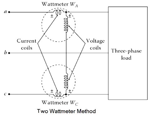
The wattmeter is an instrument for measuring the electric power (or the supply rate of electrical energy) in watts of any given circuit.
A wattmeter is a device that has a potential coil and a current coil, which are designed and connected in such a way that its pointer’s deflection is proportional to Vlcosφ. Here, V is the RMS value of the voltage applied across the potential coil, I is the RMS value of the current passing through the current coil, and φ is the angle between the voltage and the current phasors involved.
Hence a wattmeter shows a reading which is proportional to the product of the current through its current coil, the p.d. across its potential or pressure coil, and cosine of the angle between this voltage and current.
The current coil of each wattmeter carries the current of one phase only and the pressure coil measures the phase-voltage of this phase. Hence, each wattmeter measures the power in a single phase. The algebraic sum of the readings of three wattmeters must give the total Bower in the load.
The direction in which the pointer deflects depends on the instantaneous polarity of the current-coil current and the potential-coil voltage. Thus, each coil has one terminal with a polarity mark +, as shown in Figure. The wattmeter deflects in the right direction when the polarity-marked terminal of the potential coil is connected to the phase in which the current coil has been inserted.
If the load is delta connected, each wattmeter has its current coil connected on one side of the delta and its potential coil connected line to line. If the load is wye connected and the neutral wire does exist, the potential coil of each wattmeter is connected between each phase and the neutral wire.
However, in actual practice, it may not be possible to have access to either the neutral of the wye connection or the individual phases of the delta connection in order to connect a wattmeter in each of the phases.
Ques.35. Which of the following is a magnetic material in which a permanent atomic magnetic dipole has a parallel orientation?
Ferromagnetic✓
Diamagnetic
Paramagnetic
Ferrimagnetic
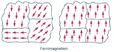
Ferromagnetic materials are the most useful magnetic materials. These derive their name from iron (Ferrum) as the most common ferromagnetic material. The relative permeability of ferromagnetic materials is much larger than 1 and can be in the thousands or higher. Some typical ferromagnetic materials are iron, cobalt, and nickel.
Ferromagnetic materials tend to magnetize in the direction of the magnetic field and some of them retain this magnetized lion after the external magnetic field has been removed. When they do so, and the magnetization is permanently retained, the material becomes a permanent magnet.
An additional important property of ferromagnetic materials is the dependence o magnetization on the level of the external field. Thus, magnetization in ferromagnetic materials is a nonlinear process.
When a ferromagnetic substance is kept in the magnetic field, the permanent alignment of the domain due to a strong interaction (force) takes place between adjacent atoms in regions called magnetic domains.
In these domains, large numbers of atoms are aligned parallel to each other so that the magnetic force within the domain is strong. When a ferromagnetic material is in the unmagnetized state, the domains are nearly randomly organized and the net magnetic field is zero.
ANTl-FERROMAGNETIC MATERIALS
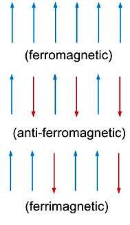
If the alignment of the dipoles is compensatory so as to give zero net moments, the material is termed anti-ferromagnetic. Such a phenomenon is termed antiferromagnetism ). For example, MnO is anti-ferromagnetic.
FERRIMAGNETIC MATERIALS
When the magnetic dipoles are oriented in the parallel and antiparallel direction in unequal numbers, so that there is a net magnetic moment, ferrimagnetism is observed.
All ferromagnetic, anti-ferromagnetic and ferrimagnetic substances transform to the paramagnetic material at certain characteristic temperatures. This happens due to the randomization of the spins at higher temperatures.
Ques.36. Three identical coils, each with a 10-ohm resistor and a 0.03-H inductor, are connected in delta across a 440-V, 50-Hz, three-phase power supply. What will be the total power consumed?
10 kW
29.11 kW
32.098 kW✓
50.41 kW
Given
Inductance L = 0.03 H
Resistance R = 10 Ω
Line voltage VL = 440 V
Inductive Reactance XL = 2πfL
Frequency f = 50 Hz
XL = 2 × π × 50 × 0.03
XL = 9 Ω
Impedance per phase ZP
ZP = √(R2 + X2L)
ZP = √(102 + 92)
ZP = 13.45Ω
In delta connected system line voltage is equal to the phase voltage
VP = VL = 440 V
IP = Vp/Zp
IP = 440/13.45
IP = 32.71A
The power consumed by the three-phase star connected circuit is
P = 3I2p Rp
P = 3 ×32.712 × 10
32098 W = 32.098 kW
Ques.37. Find the phase voltage if a three-phase star-connected system is connected to a 400 V, 50 Hz AC supply. Assume Zph = (9.8 + j10)Ω
110.24 V
230.94 V✓
400 V
230 V
Given
Line voltage =400 V
In a three-phase star connected system, the phase voltage is
VP = VL/√3 = 400/√3 = 230.94 V
Ques.38. The insulating material used for a capacitor are _____
Paper, mica and rubber
Mica, mineral oil and ceramic✓
Ceramic, silica glass and wood
Rubber, ceramic and mica
When two conducting plates are brought closer and are separated by another plate that is made up of insulating material leads to the formation of the capacitor. The insulating material used in it is called dielectric material.
The main function of dielectric material is to store electrical energy. Thus dielectric materials are used in capacitors. There are four types of capacitors available depending on the dielectric material used in them.
1. Capacitors with air and gases as dielectric:- Such capacitors are used in circuits where energy loss in them should be low as well as the value of capacitance should be small. Thus, these types of capacitors are used in circuits where accuracy is the prime concern, for example, radio frequency circuits.
2. Capacitors with mineral oil as dielectric:- These capacitors give a large value of capacitance with a small amount of dielectric loss.
3. Capacitors with a combination of solid and liquid as dielectrics Paper, glass, mica, mineral oil, castor oil, etc. are used in these types of capacitors. Oil impregnated paper dielectric is used for making capacitors that should have a large value of capacitances. These types of capacitors are used in power distribution systems.
4. Capacitors with only solid as dielectric such as glass, mica, etc. These capacitors are used in laboratories. Mica has a high dielectric constant, high dielectric strength, and low dielectric loss. Further, the dielectric constant of mica does not change much with temperature. Most of the capacitors are constructed as sealed components.
Ques.39. Which one of the following materials is used for making permanent magnets?
Steel
Carbon
Cobalt-steel✓
Graphite
Properties of the material of a permanent magnet :
(1) It should have high retentivity so that it remains magnetized in the absence of the magnetizing field.
(2) It should have high saturation magnetization.
(3) It should have high coercivity so that it does not get demagnetized easily.
As steel and alnico have high coercivity, therefore, they are used for making permanent magnets. The metals in Alnico magnets are indicated by the pairs of letters making up the name, Aluminum, Nickel, and Cobalt.
Ques.40. ______ is an example of a high-resistivity material.
Copper
Gold
Silver
Nichrome✓
Electrical resistivity (also known as specific electrical resistance, or volume resistivity) is a fundamental property of a material that quantifies how strongly that material opposes the flow of electric current.
Copper, Silver, gold are good conductors of electricity hence their resistivity is low. whereas Nichrome is a resistive alloy.
Nichrome has very high resistivity (due to which the heating element made of nichrome has a high resistance and produces a lot of heat on passing current). nichrome does not undergo oxidation (or burn) easily even at high temperatures. Due to this nichrome wire can be kept red-hot without burning or breaking in the air.