Ques.41. A 20-mF capacitor is in series with a 150-ohm resistor. The combination is placed across a 40-V DC source. The time constant of the circuit is _____
- 8s
- 2.4s
- 6s
- 3s✓
The RC time constant, also called tau, the time constant (in seconds) of an RC circuit, is equal to the product of the circuit resistance (in ohms) and the circuit capacitance (in farads), i.e. τ = RC Given R = 150 ohm C = 20 mF = 20 × 10−3 τ = 150 × 20 × 10−3 τ = 3 s
Ques.42. The wattmeter method used to measure the power in a three-phase load. The wattmeter readings are 400 W and −35 W. What will be the total active power?
- 360 W
- 370 W
- 375 W
- 365 W✓
W1 = 400W W2 = −35 W Total active power = W1 + W2 = 400 + (−35) = 365 W
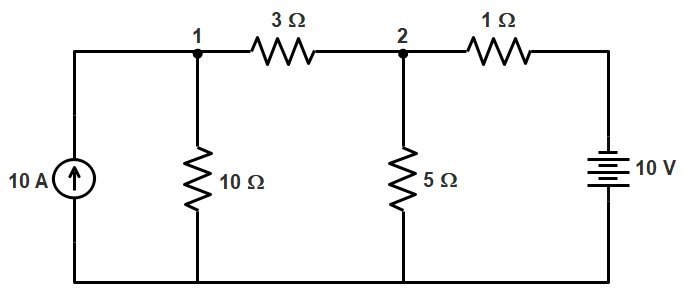
Ques.43. Find the node voltage at node 1 in the following circuit.
- 23.7 V
- 43.7 V
- 33.7 V✓
- 53.7 V
Let the node 1 be the reference node as shown in the figure below and all the current are coming out from node 1. At node 1 −3 + V1/10 + (V1 − V2)/3 = 0 = 13V1 − 10V2 = 300 At node 2 (V2 − V1)/3 + V2/5 + V2 − 10 = 0 23V2 − 5V1 = 150 or V2 = (150 + 5V1)/23 Putting the value of V2 in equation 1 we get V1 = 33.73 V V2 = 13.8 V Hence the voltage at Node 1 is 33.7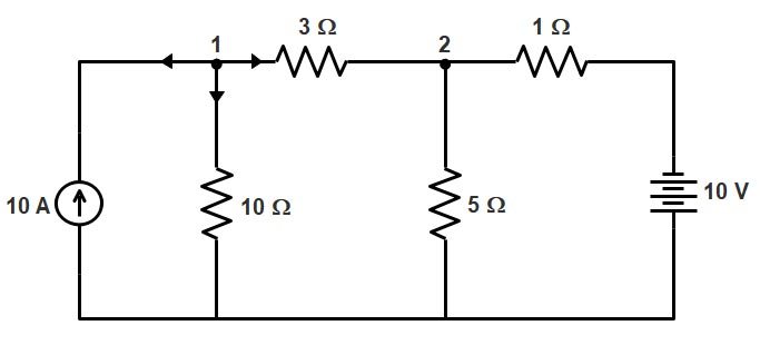
Ques.44. Which of the following leads to a low voltage and a low power factor?
- Active power
- Resistor
- Harmonic✓
- Balanced load
A pure sinusoidal waveform with zero harmonic distortion is a hypothetical quantity and not a practical one. The voltage waveform, even at the point of generation, contains a small amount of distortion due to non-uniformity in the excitation magnetic field and discrete spatial distribution of coils around the generator staler slots. The distortion at the point of generation is usually very low, typically less than 1.0%. Harmonic voltages and currents in a Power System are a result of non-linear electric loads. Voltage and current waveforms in an a.c. an electrical power system is rarely perfect sinusoids. Distortion of the waveform arises when: Effect of harmonics Harmonics increase motor losses, and can adversely affect the operation of sensitive auxiliary equipment. The non-sinusoidal supply results in harmonic currents in the stator which increases the total current drawn. Electric motors experience losses due to hysteresis and losses due to eddy currents set up in the iron core of the motor. These are proportional to the frequency of the current. Higher harmonics frequencies, produce greater core losses in a motor than the power frequency would. This results in increased heating of the motor core, which (if excessive) can shorten the life of the motor. The 5th harmonic causes a CEMF (counter electromotive force) in large motors which acts in the opposite direction of rotation. The CEMF is not large enough to counteract the rotation, however, it does play a small role in the resulting rotating speed of the motor. Also, stray load losses can increase significantly at harmonic frequencies. Overall motor losses increase by about 20% with a six-step voltage waveform compared to an operation with a sinusoidal supply. In some cases, the motor may have to be de-rated as a result of the losses. Alternatively, additional circuitry and switching devices can be employed to minimize losses. Instability can also occur due to the interaction between the motor and the converter. This is especially true of motors of low rating, which have low inertia. Harmonics can also contribute to low power factor.
Ques.45. Three coils, each having a resistance of 10 ohms and an impedance of 0.02 H, are connected in the star across a 440-V, 50 Hz, three-phase power supply. What will be the phase voltage?
- 250.343 V
- 254.03 V✓
- 230 V
- 0 V
Given Line voltage =400 V In a three-phase star connected system, the phase voltage is VP = VL/√3 = 440/√3 = 254.03 V
Ques.46. The total capacitance of 10 capacitors, each of 5μF, in series, will be____
- 2 μF
- 10 μF
- 0.5 μF✓
- 5 μF
When the capacitance is connected in the series the total capacitance is equal to C = 1/C1 + 1/C2 + 1/C3 + ————-CN 1/C = 1/5 + 1/5 + 1/5———- + 1/510 1/C = 10/5 C = 0.5
Ques.47. In a three-phase system, the relation IL = √3Iph is applicable to a:
- Single-phase system load
- Delta-connected load✓
- Star connected load without the neutral point
- Star connected load
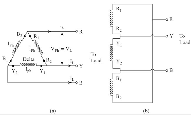
Delta Connection The delta connection is formed by connecting the end of one winding to the starting end of the other and connections are continued to form a closed loop. In this case, the current flowing through each line conductor is called line current IL and the current flowing through each phase winding is called phase current, Iph. And the line current is √3 times of phase current. IL = √3.Iph However, we find that the phase voltage is the same as the line voltage in a delta connection. The supply terminals are taken out from the three junction points. The delta connection of windings has been shown in Fig.
Ques.48. Hard magnetic materials are used for maufacturing______
- Temporary magnets
- Permanent magnets✓
- Conductors
- Insulator
Properties of the material of a permanent magnet : (1) It should have high retentivity so that it remains magnetized in the absence of the magnetizing field. (2) It should have high saturation magnetization. (3) It should have high coercivity so that it does not get demagnetized easily. Hard Magnetic material The resistance to the moment of the magnetic domain walls is large. The causes for such a nature are also due to the presence of impurities of non-magnetic materials or the lattice imperfections. The presence of defects increases the mechanical hardness to the material and an increase the electrical resistivity and reduces eddy current losses. But if it gets magnetized, it will be permanently magnetized. Hard magnetic materials are characterized by (i) high remanent magnetization (ii) high coercivity (iii) high saturation flux density (iv) low permeability (v) high hysteresis loss. Most widely used permanent magnetic materials are low alloy steels containing 0.658 to 1% carbon. Other materials are (1) Alnico [an alloy of Al, Ni, Co, Cu, and Fe] (2) Tungsten steel alloy (3) Platinum-cobalt alloy (4) Invar, etc. Hard magnetic materials are used to prepare permanent magnets. Most of them are manufactured from alloys of steel with tungsten and chromium.~Ihe permanent magnets are used in magnetic separators, magnetic detectors, in speakers used in audio systems and microphones. Hard magnets made of carbon steel find application in the making of magnets for toys and certain types of measuring meters because of its low cost. [ninja_tables id=”28691″]
Ques.49. A lead-acid battery should NOT be discharged beyond_____
- 3.75 V
- 2.2 V
- 1.8 V✓
- 5 V
Battery cycle and depth of discharge One discharge and charge period are referred to as a battery cycle. A major factor affecting battery life is the depth of discharge i.e. how much the battery is discharged and how often. The depth of discharge of a battery is a measure in the percentage of the amount of energy which can be removed from a battery during a cycle. Limiting the depth of discharge will make the battery last longer. If discharged beyond its recommended depth of discharge, the life of a battery will be considerably reduced. It is suggested that lead-acid batteries not be discharged beyond 80%, even if the battery is designed for deep discharge. Lead acid batteries that are deeply discharged may suffer from a permanent loss of capacity due to sulphation, acid dilution and the greater tendency for freezing. The fully charged lead-acid cell has 2.25 Volts. The 80% of this voltage is nearly to 1.8 Volts. Maintenance of Lead-Acid Batteries In order to ensure long life and efficient service, proper maintenance of lead-acid batteries is of utmost importance. These are some of the general instructions that need to be followed: (i) The level of electrolyte should be checked regularly. Electrolyte needs to be evaporated by adding distilled water only. (ii) The status of the charge of battery needs to be checked regularly. The specific gravity of electrolyte should be periodically measured through hydrometer. Lead-acid batteries should not be discharged beyond a terminal voltage of 1.8 V per cell and specific gravity of electrolyte should not fall below 1.1V (iii) A battery need not be left in a discharged state for a long time. The reason being lead sulfate formed on the plate crystallizes and makes restoration of the battery to its full capacity difficult. Sulphation excess for a long period makes the battery useless. (iv) The charge and discharge current should not be allowed to overheat the battery with electrolyte temperature exceeding a limit of 45°C. It mainly results in the wrapping of the battery plates and excessive sulphation. (v) The battery terminals should not be shorted to test it. It will cause a very high current which may overheat the battery, melt the short link end covering the battery plates. (vi) Battery terminal needs to be kept clean, dry and coated with petroleum jelly or other battery preparation. This prevents the corrosion of metal work. Be sure that the vent holes in the caps are open and battery connections are tight. (vii) Battery charging should be carried out in a well-ventilated place so as to avoid suffocation caused due to gases and acid fumes. (viii) The naked flame needs to be kept away at all the times from the battery. Battery connection should not be disturbed when the supply is charging as there is a risk of sparkling. It is necessary that precautions are taken in order to avoid the possible explosion of the gaseous mixture which may be present in the vicinity of the battery. (ix) if the battery is not being used regularly it should be put on trickle charge. (x) It is advised not to spill the electrolyte. It is advised to protect your eyes, skin, and clothes.
Ques.50. The time constant value in an R-L circuit is given by:
- vit
- RC
- iR
- L/R✓
The time constant represents the time required for the charge to increase from zero to 63.2% of its maximum equilibrium value. An LR Series Circuit consists basically of an inductor of inductance L connected in series with a resistor of resistance R. Time Constant The time constant of an RL circuit is defined as the time taken by the inductor current to reach steady state if initial rate of rise is maintained. or The time constant of RL circuit is defined as the amount of time necessary for current in the circuit to reach 63.2% of its maximum value. or The time constant of a series RL circuit equal to the ratio of the value of inductor to the value of resistance τ = L/R Where T = time constant in seconds,
L = inductor in Henry,
R = resistance in ohms.