DMRC Junior Engineer Previous Year Electrical Question Paper with explanation and Solution 10th- April- 2018
Ques 1. The type of electrode used in the seam welding is
- Bare wire Rods
- Roller electrodes✓
- Heavily coated electrode
- Lightly covered electrode
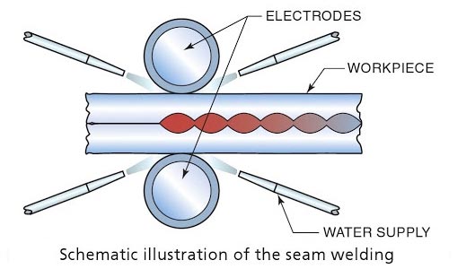
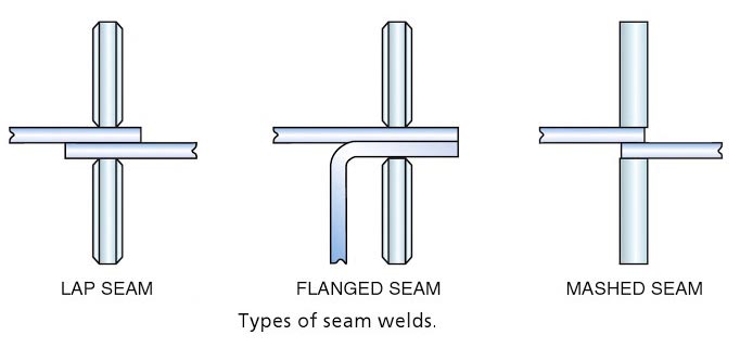
Welding electrode. A component of the welding circuit through v hick current is conducted and that terminates at the arc, molten conductive slag, or base metal. See also arc welding Electrode (arc welding)—a “stick” or ~wire” from which an arc is struck. It may include the bare metal electrode, carbon electrode, composite electrode, covered electrode, lightly coated electrode and the heavy coated electrode. Electrode (resistance welding)—that part or parts of a machine through which the welding current and in most cases, pressure, are applied directly to the work. The electrode may be in the form of a rotating wheel, bar, cylinder, plate, clamp. In principle, this process is similar to spot welding except for the shape of the electrodes. In seam welding, continuously rotating disc type electrodes . are used whereas in spot welding pointed electrodes are used. In seam welding pressure is applied. In seam welding pressure is applied continuously along the whole length of the lap joint to produce a seam weld. The metallic pieces a held in two copper disc roller electrodes and are passed through them to complete the joint. Seam welding is accomplished by using roller-type electrodes in the form of wheels that are 6 in. (152 mm) to 9 inches. (229 mm) or more in diameter. These roller-type electrodes are usually copper alloy discs 3/8 inch (10 mm) to 5/8 inch (16 mm) thick. Cooling is achieved by a constant stream of water directed to the electrode near the weld. Welding is done either with the roller electrodes in motion or while they are stopped for an instant. If the continuous motion is used, the rate of welding usually varies between 1 ft and 5 ft (30 cm to 152 cm) per minute. The greatest welding speed is obtained on the thinnest materials. An indexing mechanism can be used when the wheels are to be stopped for each weld. Electric timing equipment is used when it is necessary to provide the precise control required for highest quality welds. Spot welds can be positioned at almost any interval desired by simply adjusting the timing and rate of electrode motion. It is possible to change the welding current and electrode pressure to control the surface condition and width of the weld. The seam width should be about two times the thickness of the sheet plus 1/16 inch (2 mm). Types of Resistance Seam Welds The figure illustrates the type of seams used in most seam welding processes. The lap seam is the most common of these seams. The tops and bottoms of containers are usually fastened together with a Hanged seam. For a metal thickness of 1/16 inch (2 mm), the mash seam is often used. The electrode face should be wide enough to cover the overlap by approximately one and a half times the thickness of the sheet. This process is similar to RSEW in some ways. TO major differences are that the welding current is supplied as supplied frequency, 200 to 500 kHz as opposed to DC 50-cycle AC. The high-frequency power provides very localized heating. This heating is a result of the resistant to the current induced in the metal and not to the resistance between parts. As a consequence of this localizes heating, pipe and tubing can be welded with little loss of power flowing around the back side of the joint. High-Frequency Resistance Seam Welding is used in the production of welded pipe tubing, and structural shapes. It works very well for tip fabrication of l-beams, H-beams, channels, and so on. The welded structural shapes are lighter and stronger than the roll-formed counterparts.Seam Welding
High-Frequency Resistance Seam Welding
Ques 2. Calculate the length of the wire required for an electric radiator to dissipate 1 kW when connected to a 230 V supply, if the coils of the radiator are made of wire 0.5 mm in diameter having the resistivity of 60 μΩ.cm
- 400 cm
- 753 cm
- 1732 cm✓
- 1456 cm
Given As we know that power P is given by P = V2 ⁄ R R = 2302 ⁄ 1 × 10³ R = 52.9 Ω For any given material at a certain given temperature, the resistance is given as where ρ is a constant and known as its specific resistance or resistivity. l = Length in Meter a = area of cross-section in m2 R = Resistance in Ohm Therefore L = RA ⁄ ρ = $\begin{array}{l}l = \dfrac{{52.9 \times \dfrac{\pi }{4} \times {{(0.5)}^2} \times {{10}^{ – 6}}}}{{60 \times {{10}^{ – 6}} \times {{10}^{ – 2}}}}\\\\{\text{L = 17}}{\text{.311 m}}\end{array}$
Power P = 1 kW
Voltage V = 230 V
Diameter d = 0.5 mm
Resistivity ρ = 60 μΩ.cm
Area a = π/4.d2
Ques 3. In the case of an electromechanical generator, the frequency is
- Directly proportional to the voltage
- Indirectly proportional to the speed
- Directly proportional to the speed✓
- Indirectly proportional to the power
Electromechanical devices are reluctance motor, synchronous Motor, induction Motor, etc. A dc generator produces a voltage level proportional to the speed while the AC motor produces a voltage level proportional to the frequency. The synchronous speed of an alternator is given as Ns = 120f/P Where f = frequency Large electric power grids are complex dynamical systems, displaying electromechanical coupling on a nearly continental scale. Electrical frequencies are among the key output variables reflecting electromechanical behavior. At locations with synchronous generation attached, the inherent physics of the synchronous machine dictate that the electrical frequency of the generator voltage and mechanical rotational speed of the generator are locked in fixed proportion to each other, so that variation of frequency directly reflects deviations in rotational speed away from the desired steady state.
P = number of poles
Ques 4. Which of the option is INCORRECT for the following statement.
Three resistances are said to be in parallel when
- The total current is the sum of three parallel current
- All the resistance are connected end to end✓
- The potential difference across all the resistance is the same
- The current in each resistor is different and maybe calculated by ohm law.
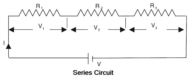
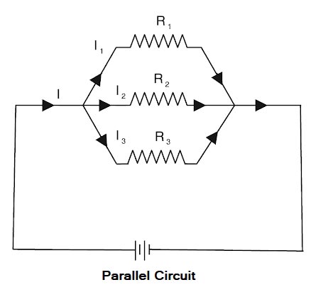
The resistance can be combined in two ways: Series Circuit When two or more resistance is connected ends to end consecutively, they are said to be connected in series. Resistances are said to be connected in series when there exists only one path for the flow of current and the current through each resistor is equal. CHARACTERISTICS OF SERIES CIRCUITS In series circuits, (1). The sum of the voltage drops across the individual circuit components is equal to the applied voltage. (Voltage drops add.) Vtotal = V1 + V2 + V3 (2). The total current flow through each resistance or load. The mathematical formula is as follows: ITotal = I1 = I2 = I3 The total resistance is equal to the sum of all resistive components in the circuit. (Resistance adds.) The formula for calculating total resistance in a series circuit is as follows: Rtotal = R1 + R2 + R3 Resistance in Parallel When two or more resistances are connected between the same two points they are said to be connected in parallel. The below figure shows three resistances R1, R2, and R3 Two or more resistors are said to be connected in parallel when one end of each resistor is connected to the positive pole and the other end to the negative pole of the common battery or voltage source. Characteristics of a parallel circuit (i) The potential drop across each resistance is the same. VTotal = V1 = V2 = V3 (ii) The reciprocal of the effective resistance is equal to the sum of the reciprocals of the individual resistances. 1/Rtotal = 1/R1 + 1/R2 + 1/R3 (iii) The current is divided between the different loads according to their individual resistances, and the total current is equal to the sum of the currents in each branch. The mathematical formula is as follows: Itotal = I1 + I2 + I3 (iv). The effective resistance is less than the least resistance in the circuit. (v) Maximum power is consumed by the least resistance, or the maximum current flows through the least resistance.
Ques 5. For zero power factor leading loads, the effect of armature reaction in an alternator is
- Distortion
- De-magnetizing
- Cross Magnetizing
- Magnetizing✓
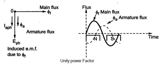
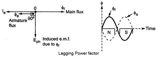
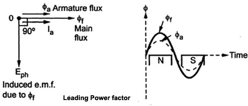
When the load is connected to the alternator, the armature winding of the alternator carries a current. Every current-carrying conductor produces its own flux so the armature of the alternator also produces its own flux when carrying a current. So there are two fluxes present in the air gap, one due to armature current while the second is produced by the field winding called main flux. The flux produced by the armature is called armature flux So the effect of the armature flux on the main flux affects its value and the distribution is called armature reaction. The effect of the armature flux not only depends on the magnitude of the current flowing through the armature winding but also depends on the nature of the power factor of the load connected to the alternator Consider a purely resistive load connected to the alternator, having a unity power factor. As induced e.m.f Eph drives a current Iph and load power factor is unity, Ephand Iph is in phase with each other. If φf is the main flux produced by the field winding responsible for producing Ephthen Eph lags φf by 90°. Now current through armature Ia produces the armature flux say to,, So flux φa, and la are always in the same direction. It can be seen from the phasor diagram that there exists a phase difference of 90°between the armature flux and the main flux. From the waveforms, it can be seen that the two fluxes oppose each other on the left half of each pole while assisting each other on the right half of each pole. Hence average flux in the air gap remains constant but its distribution gets distorted. Hence such distorting effect of armature reaction under unity p.f. the condition of the load is called the cross magnetizing effect of armature reaction. Due to such distortion of the flux, there is a small drop in the terminal. Consider a purely inductive load connected to the alternator having zero lagging power factor. This indicates that Iph driven by Eph lags Eph by 90° which is the power factor angled. Induced e.m.f. Eph lags main fluxes φf by 90° while φa is in the same direction as that of Ia. It can be seen from the phasor diagram that the armature flux and the main flux art exactly in the opposite directions to each other. So armature flux tries to cancel the main flux Such an effect of armature reaction is called the demagnetizing effect of the armature reaction. As this effect causes the reduction in the main flux, the terminal voltage drops. This drop in the terminal voltage is more Man the drop corresponding to the unity p.f. load. Consider a purely capacitive load connected to the alternator having zero leading power factor. This means that armature current Iaph driven by Eph leads Eph by 90° which is the power factor angle φ. Induced e.m.f. Eph lags φf by 90° while Iaph and φa, are always in the same direction. The armature flux and the main field flux are in the same direction i.e. they are helping each other. This results in the addition of main flux. Such an effect of each armature reaction due to which armature flux assists field flux is called the magnetizing effect of the armature reaction As this effect adds the flux to the main flux, greater e.m.f. gets induced in the armature Hence there is an increase in the terminal voltage for leading power factor loads. For intermediate power factor loads i.e. between zero lagging and zero leading the armature reaction is partly cross magnetizing and partly demagnetizing for lagging power factor loads or partly magnetizing for leading power factor loads.Armature Reaction
Unity Power Factor Load (Cross-Magnetizing)
Zero Lagging Power Factor Load (Demagnetizing)(Over-excited)
Zero Leading Power Factor Load (Magnetizing) Under-excited
Ques 6. Synchronous Motor for the rotary Kilns Run at
- Ultra high speed
- Ultra Low speed✓
- Low Speed
- Medium speed
Synchronous motors have the following advantages as compared to 3-phase induction motors :
Ques 7. In a balanced 3-phase system, the zero-sequence current is
- Zero✓
- Maximum
- Minimum
- Varying
In a balanced three-phase system there exist only the positive phase sequence component; the negative and zero sequence component are always zero. A balanced three-phase system voltage supply consists of three individual sinusoidal voltages that are all equal in magnitude and frequency but are out-of-phase with each other by exactly 120o electrical degrees. The phase voltages are all equal in magnitude but only differ in their phase angle. The three windings of the coils are connected together at points, a1, b1 and c1 Then Red phase VRN = Vm sinθ In a 3-Phase system, the presence of negative or zero sequence currents introduces un-symmetry and is indicative of an abnormal condition of the circuit in which these components are found. In the case of unbalanced 3 phase faults, we represent it as the sum of 3 balanced phasors (so-called sequence components). Positive sequence component: It indicates three equal phasors which are 120 degrees apart and has the same phase sequence as the original signal. In our case, this will be the source/supply current/voltage. If our phase sequence is RYB then it will be in the RYB sequence. It specifies that the current is flowing through the source to load. Negative sequence component: It indicates three equal phasors which are 120 degrees apart and has opposite phase sequence as the original signal. If supply is RYB then these will be in RBY sequence. It specifies that current is flowing from load to source. Zero sequence component: it represents three equal and parallel phasors with zero degrees phase displacement. It specifies that current is flowing from source to ground.
Yellow Phase VYN = Vm sin(θ – 120°)
Blue Phase VBN = Vm sin(θ – 240°)
or VBN = Vm sin (θ + 240°)
Ques 8. The series field of the long shunt compound generator is excited by
- Supply current
- Field current
- Load current✓
- Armature current
Compound Generator Voltage regulation of the series generator is very poor but the ability to produce additional useful magnetism in response to increased load is very good. This useful characteristic of the DC series generator and the constant voltage characteristic of the shunt generator are combined in the compound generator. As we know that the terminal voltage of the DC generator decreases as the load on the generator is increased. The compound generator was developed to eliminate this problem. In some applications this drop is admissible but in the case of lighting loads, it presents a serious problem. For example, in ships, the same generator is used to supply the power to DC machinery as well as to the lighting circuits. So, when the load increases, the terminal voltage decreases. Hence. depending on the load, the generator continually fluctuates. These variations in current produce corresponding changes in the generator terminal voltage, resulting in the flickering of light. A compound generator eliminates this problem. In a compound wound generator, there are two sets of field windings on each pole one is in series and the other is in parallel with the armature. There art two types of compound generators: Short-shunt compound generator in which only shunt field winding is connected in parallel with the armature, as shown in Fig. In short shunt connection series, field carries no current at no-load and thus its open-circuit characteristics are the same as that of a shunt generator. The current relations of the short-shunt connection of a d.c. compound generator is la = If + IL Where Ia = Armature current Long-shunt compound generator in which the shunt field is connected in parallel will both the series winding and the armature, as shown in Fig. In long shunt connection, the series field winding carries the current same as that of shunt field winding at no-load. The current relations of the long-shunt connection of a d.c. compound generator is la = If + IL Two fields of the compound generators may be cumulative or differential wounds. If it is cumulative the two fields are additive and the two fields are subtractive if it is a differential wound. The essential difference between the two is that in the short-shunt connection, the armature current excites the series field, whereas, in the long-shunt connection, the load current excites the series field.

If = Field current
IL = Load current
Ques 9. According to double-revolving field theory, a sinusoidal alternating flux can be looked upon as the combination of two revolving fluxes
- Equal in magnitude to that of the alternating flux, rotating at the synchronous speed in opposite direction.
- Of half the magnitude to that of the alternating flux, rotating at the synchronous speed in opposite direction.✓
- Of half the magnitude to that of the alternating flux, rotating at the synchronous speed in the same direction
- Equal in magnitude to that of the alternating flux, rotating at the synchronous speed in the same direction.
The working principle of an ac machine is primarily “one field following another field”. In the case of a multiphase induction motor, there will be a virtual rotating magnetic field. But considering the case of a single-phase induction motor, it’s only a pulsating field that is produced and not a rotating one. This can also be explained on the basis of ‘DOUBLE REVOLVING FIELD THEORY‘, which is based on the Ferraris Principle As per Ferrari’s principle, the alternating magnetic field produced by the stator can be split into two rotating magnetic fields of half the magnitude and rotating at synchronous speed in opposite directions. When the alternating supply is fed to the stator winding, an alternating flux is developed This flux rotates and cuts the rotor conductors. Due to this, an EMF is induced. As the rotor circuit is closed the current flows through the rotor conductor. This rotor current will cause rotor flux and at any instant, its magnitude is given by, φs = φm COS ωt where φm is the maximum flux developed in the motor. According to this theory, the alternating flux φs can be resolved into two components and φf & φb such that the magnitude of by φf & φb is equal to half the magnitude of φs . Let us assume that φf rotates in a clockwise direction and φb rotates in the anti-clockwise direction. An emf is induced in the rotor circuit due to each rotating field. If the polarity of the induced emf in the rotor due to φf is taken as positive then emf induced in the rotor due to φb is negative (i.e. in phase opposition). As, at standstill, the slip in either direction is the same (i.e. s = 1), the rotor impedance will also be the same. Thus, the rotor currents are equal, but opposite in phase that is the starting torque developed by each revolving field is the same, with one acting in forwarding direction and the other acting in the backward direction. Thus, the net torque developed by the motor is zero. Based on double-revolving field theory, a single-phase induction motor can be visualized as having two rotors revolving in opposite directions with a common stator winding. At standstill, the two rotors develop equal torques in opposite directions and hence the net torque developed is zero.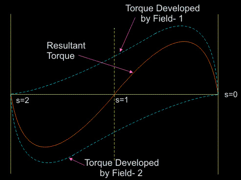
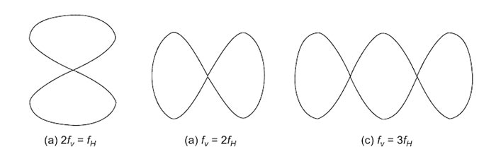
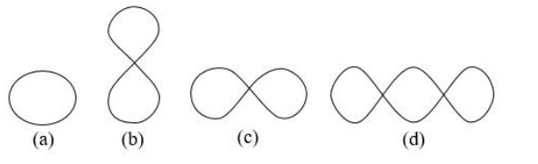
Ques 10. From the given Lissajous patterns obtained while measuring frequency using a cathode ray oscilloscope (CRO), select the pattern which indicates the relationship fv = 1⁄2fh
- (a)
- (b)✓
- (c)
- (d)
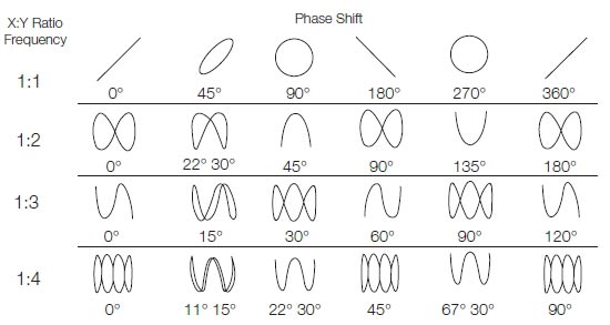
Lissajous Figures Lissajous figures are a family of parametric 2D curves frequently used to establish the frequency ratio or relative phase between two harmonic signals. They were initially investigated by Nathaniel Bowditch in 1815, and later in more detail by Jules Antoine Lissajous in 1857. The Lissajous pattern method is the quickest method of measuring the frequency. In this method, the standard known frequency signal is applied to horizontal plates and the simultaneously unknown frequency signal is applied to the vertical plates. The shape of Lissajous figures depends on: If sinusoidal voltages are applied to both vertical and horizontal inputs of CRO, some interesting figures are displayed, which are known as Lissajous figures. or Lissajous figures are formed when two sine waves are applied simultaneously to the vertical and horizontal deflecting plates of a CRO. Two sine waves of the same frequency produce a Lissajous figure which may be a straight line, an ellipse or a circle, depending on the phase and amplitude of the two signals. Two sine waves of equal amplitudes but different frequencies will produce a figure from which the relationship between the two frequencies can be understood. For example, Fig.(a) shows that the vertical input signal has twice the frequency of the horizontal input signal. Similarly, Fig.(b) indicates that the horizontal input signal has twice the frequency of the vertical one. Fig.(c) shows three loops indicating that the vertical input signal has thrice the frequency of the horizontal one. A known frequency (fH) is applied to the horizontal input an unknown frequency (fv) to the vertical input. Then a Lissajous pattern with loops is obtained. The unknown frequency (fv) can be measured by the following relationship. (fv)/(fH) = No. of loops cut by horizontal line ⁄ No. of loops cut by a vertical line The various Lissajous figures for the different ratios are shown below