NMRC JE ELECTRICAL SOLVED PAPER WITH EXPLANATION 2017
Ques 1. The EMF Induced in the coil of N turns is given by:
e = Ndt/dφ
e = −Ndφ/dt✓
e = Ndφ/dt
e = dφ/dt
Faraday’s laws of induction imply that the emf induced in a coil of N turns is directly related to the rate of change of flux through it. i.e
e = −Ndφ/dt
where dφ is the change in flux in Webers, and dt is the time taken for the flux to change in seconds (i.e. dφ/dt is the rate of change of flux).
The minus sign indicates that the induced e.m.f. is in such a direction as to oppose the change producing it.
Ques 2. The element which is capable of delivering energy on its own is known as:
Non-Linear elements
Unilateral elements
Active element✓
Passive element
The active elements generate energy. Batteries, generators, operational amplifiers etc are active elements.
Ques 3. When a high voltage Overhead line passes over or adjacent to any building the vertical clearance between the highest part of the building immediately under such lines, recommended in IE rules is of not less than:
1.2 m
2.8 m
6 m
3.7 m✓
Where a high or extra high voltage over headline passes above or adjacent to any building or part of a building, it shall have on the basis of maximum sag, a vertical clearance above the highest part of the building immediately under such line, of not less than:
For high voltage line upto and including 33 KV the vertical clearance is about 3.685 meters i.e 12 ft.
For extra high voltage lines, the vertical clearance is 13ft.
Ques 4. A billion electron passes through a conductor of cross-section area in 10-3 sec. The current is
10-7 A
2.6 x 10 -3 A
2 x 10 -4 A
1.6 x 10 -7 A✓
1 ampere is the flow of 1 coulomb of charge in 1 second
1 billion = 1 x 10⁹
1 electron has a charge of 1.6 × 10⁻¹⁹. A billion electrons thus have a total charge of about 1.60 ×10 −19 × 109= 1.60 × 10⁻¹⁰C.
One milli-second = 10-3 sec.
= 1.60 × 10⁻¹⁰/10-3 = 1.60 × 10⁻⁷.
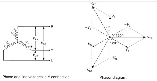
Ques 5. In a star connected balanced circuit the phase difference between the line voltage VRY and the phase voltage VR is equal to
90°
60°
120°
30°✓
In a star connection, we know that each phase is displaced in space by 120° from each other.
From the above phasor diagram, the phase the LINE VOLTAGE LEADS PHASE VOLTAGE BY AN ANGLE 30°
Ques 6. In a CRO, when set for internal trigger (INT)
Trigger circuit will input vertical amplifier
Trigger circuit receives input from the horizontal amplifier
Trigger circuit will input Horizontal Amplifier
Trigger circuit receives input from the vertical amplifier✓
The whole process of producing the saw-tooth wave, at the moment pulses are provided is called the triggering. Correct triggering is required for obtaining a steady display of the input voltage wave on the CRO screen. So, triggering the sweep generator at the correct time means working in synchronism with the input voltage wave. Synchronization of the sweep waveform with the input measurement signal is easily achieved by obtaining the trigger signal from the input signal. This is called “internal triggering” Rather than using the input signal, an external signal can also be used for triggering.
The trigger circuit is of two types
External Triggering
Internal Triggering
The input signal may come from an external source when the trigger selector switch is set to EXT, from a low amplitude ac voltage at line frequency when the switch is set to line. The condition that should satisfy for external triggering is that the frequencies of the triggering signal and the external signal.External triggering is necessary when the amplitude of the measured signal is too low. Such weak signals will not be able to drive the pulse generator and hence internal triggering may not be possible.
When set for internal Triggering INT, the trigger circuit receives its input from the vertical amplifier. When the vertical input signal that is being amplified by the vertical amplifier matches a certain level, the trigger circuit provides a pulse to the sweep generator, thereby ensuring that the sweep generator output is synchronized with the signal that triggers it.
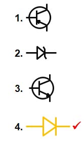
Ques 7. The schematic symbol for a PN junction diode is
Ques 8. An 8H choke is carrying a current of 500 mA. The energy supplied by Inductor is
2 J
4J
0.5 J
1J✓
Energy stored in the Inductor = LI2/2
where
W = energy stored (joules, J)
L = inductance (henrys, H)
I = current (amps, A)
= 8 × 0.52 /2 = 1 J
Ques 9. The type of wattmeter commonly used for the measurement if Power in an AC circuit is
Moving Iron type
Thermocouple Type
Rectifier Type
Dynamometer Type✓
A wattmeter is an instrument used to measure the measure active power supplied to a circuit. Induction type Wattmeter is used to measure A.C. power only in contrast to dynamometer wattmeter which can be used to measure D.C. as well as A.C. power.
Dynamometer type wattmeter reads directly the average power dissipated in the load. It can be used to measure reactive power as well as power factor of the load. This wattmeter can measure active and reactive power if the waveforms being measured are not sinusoidal. It can also be used to measure power consumption in d.c.
Note:- Although the Rectifier and thermocouple are also used to measure the A.C power but they do not come under in the wattmeter category.
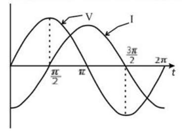
Ques 10. The Waveform showed Below Indicate
V lags I by π
V leads I by π
V lags I by π/2
V leads I by π/2✓
From the above wave-form, we can conclude that the Voltage reaches its peak value first and the difference between the peak value angle of current and voltage is π/2. Hence the voltage leads current by an angle of π/2. It is a purely inductive circuit waveform.