
DMRC Junior Engineer Previous Year Electrical Question Paper with explanation and Solution -2018
Ques 1. Solid state power supplies are protected from medium surge voltage using:
- Zinc-oxide-Based Varistor✓
- Cermet Resistor
- Metal Glaze resistor
- Silicon carbide resistor
Note:- A linear resistor is one that obeys Ohm’s law. A circuit that contains only linear components is called a linear circuit. A cermet is a composite material composed of ceramic and metal materials. A cermet is ideally designed to have the optimal properties of both a ceramic, such as high-temperature resistance and hardness, and those of a metal, such as the ability to undergo plastic deformation. The cermet resistor can be obtained by depositing highly stable metallic solutions (like silver/gold with palladium or chromium with silicon monoxide or oxides of rhodium/zirconium) in an organic solvent on the ceramic substrate. This is done by micro screen printing, roller printing, or dipped proceed. When the substrate la heated (1000°C), the organic particles evaporate and the metal fuses into the ceramic substrate. Advantaged Cermet resistors are offering the following advantages. The metal glaze resistor is also a fixed resistor, similar to the metal film resistor. This resistor is made by combining metal with glass. The compound is then applied to a ceramic base as a thick film. The resistance is determined by the amount of metal used in the compound. Tolerance ratings of 2% and 1% are common. For most materials, a very high sheet resistance can only be obtained by using an extremely thin film. By using a composite material such as a metal glaze, a thick and therefore more stable high ohmic film can be made. Such a film is produced by dipping the ceramic rod in a paste and drying and firing the layer. As cylindrical resistors, cermet or metal glaze resistors are mostly used for high-resistance values and high voltages. The available resistance range is 100 kΩ to 100 MΩ. The stability is good and the current noise is acceptable for such high values. The resistance of the metal glaze resistor depends on the amount of metal and glass added Silicon Carbide is the only chemical compound of carbon and silicon. It was originally produced by a high-temperature electrochemical reaction of sand and carbon. Silicon carbide resistors are mechanically rugged and can stand high temperatures and overload current, thus silicon carbide resistors are widely applicable in various automatic devices. The electrical conduction of the material has led to its use in resistance heating elements for electric furnaces, and as a key component in thermistors (temperature variable resistors) and in varistors (voltage variable resistors).Varistor
Cerment Resistor
Cermet or Metal Glaze Resistors
Metal glaze film with a higher amount of metal particles and a lower amount of glass provides low resistance to the electric current. Hence, a large amount of electric current flows through the metal glaze resistor.Silicon carbide resistor
Ques 2. Lightning arrester connected to a power system protects electrical equipment from
- Over-voltage due to indirect lightning stroke✓
- Direct stroke of lightning
- Frequency fluctuation
- Overcurrent due to indirect lightning stroke
Types of Lightning Strokes There are two main types of lightning strokes that appear on various equipment in the power system. They are viz. Direct Stroke and Indirect Stroke. Direct stroke may appear on line conductor, on tower top or on the ground wire indirect stroke may appear on overhead line conductors. Direct Stroke on Overhead Conductors These strokes are most dangerous as their effects are most severe and harmful. In this type of stroke, the discharge or the current path is directly from the cloud to the overhead line. From the line, the current path may be over the insulators down the pole to the ground. The voltage set up is in millions which can cause flashover and puncture of insulators. The insulators may get shattered till the surge is sufficiently dissipated and it travels to both sides. The wave may reach the substation and damage the equipment because of excessive stress produced. The earthing screen and the ground wire provide protection against direct lightning strokes but do not provide any protection against travailing waves which may reach the electrical apparatus. The lightning arresters or the surge arresters are the ones who provide protection against the travailing waves. Indirect Strokes The effect of indirect strokes is similar to that of direct strokes. Their effect is more severe in the case of distribution lines than in the case of high voltage lines. These strokes are due to electrostatically induced charges on the conductors due to the presence of charged clouds. Sometimes currents may be induced electromagnetically due to lightning discharge in the immediate vicinity of the line which results in an indirect stroke. Lightning Arrester A lightning arrester is a device used in electrical power systems and telecommunications systems to protect the insulation and conductors of the system from the damaging effects of indirect lightning stroke. The arrester provides a low-impedance path to the ground for the current from a lightning strike or transient voltage and then restores to normal operating conditions. Lightning arresters are two-terminal devices in which one terminal is connected to the power line, and the other is connected to the ground. The path from line to ground is of high resistance that it is normally open. However, when lightning, which is a very high voltage, strikes a power line, it causes conduction from line to ground. Thus, voltage surges are conducted to the ground before a flashover between the lines occurs. After the lightning surge has been conducted to the ground, the valve assembly then causes the lightning arrester to become nonconductive once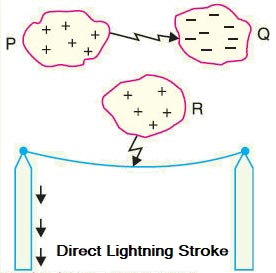
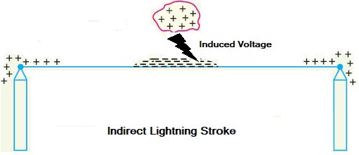
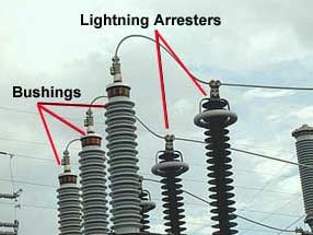
more.
Ques 3. When an alternator is over-excited, which of the following is true regarding the reactive power that flows from it?
- It’s flow Outward✓
- It’s flow Inward
- Reactive Power Neutralize the active power
- It is zero
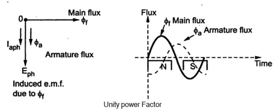
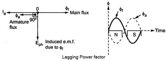
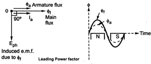
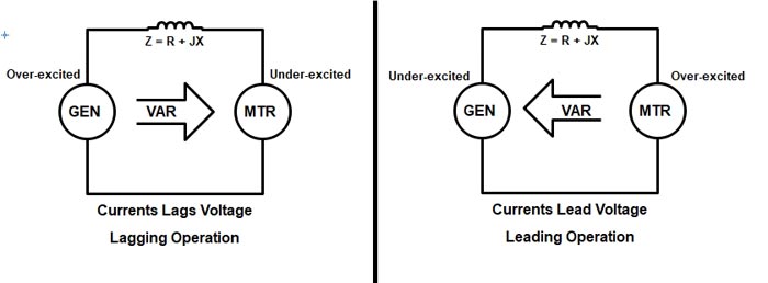
Armature Reaction When the load is connected to the alternator, the armature winding of the alternator carries a current. Every current-carrying conductor produces its own flux so the armature of the alternator also produces its own flux when carrying a current. So there are two fluxes present in the air gap, one due to armature current while the second is produced by the field winding called main flux. The flux produced by the armature is called armature flux So the effect of the armature flux on the main flux affects its value and the distribution called armature reaction. The effect of the armature flux not only depends on the magnitude of the current flowing through the armature winding but also depends on the nature of the power factor of the load connected to the alternator Consider a purely resistive load connected to the alternator, having a unity power factor. As induced e.m.f Eph drives a current Iph and loads power factor is unity, EphandIphare in phase with each other. If φf is the main flux produced by the field winding responsible for producing Ephthen Eph lags φf by 90°. Now current through armature Ia produces the armature flux say to,, So flux φa, and la are always in the same direction. It can be seen from the phasor diagram that there exists a phase difference of 90°between the armature flux and the main flux. From the waveforms, it can be seen that the two fluxes oppose each other on the left half of each pole while assisting each other on the right half of each pole. Hence average flux in the air gap remains constant but its distribution gets distorted. Hence such distorting effect of armature reaction under unity p.f. the condition of the load is called the cross magnetizing effect of armature reaction. Due to such distortion of the flux, there is a small drop in the terminal. Consider a purely inductive load connected to the alternator having zero lagging power factor. This indicates that Iph driven by Eph lags Eph by 90° which is the power factor angled. Induced e.m.f. Eph lags main fluxes φf by 90° while φa is in the same direction as that of Ia. It can be seen from the phasor diagram that the armature flux and the main flux art exactly in the opposite directions to each other. So armature flux tries to cancel the main flux Such an effect of armature reaction is called the demagnetizing effect of the armature reaction. As this effect causes the reduction in the main flux, the terminal voltage drops. This drop in the terminal voltage is more Man the drop corresponding to the unity p.f. load. Consider a purely capacitive load connected to the alternator having zero leading power factor. This means that armature current Iaph driven by Eph leads Eph by 90° which is the power factor angle φ. Induced e.m.f. Eph lags φf by 90° while Iaph and φa, are always in the same direction. The armature flux and the main field flux are in the same direction i.e. they are helping each other. This results in the addition of the main flux. Such an effect of each armature reaction due to which armature flux assists field flux is called the magnetizing effect of the armature reaction As this effect adds the flux to the main flux, greater e.m.f. gets induced in the armature Hence there is an increase in the terminal voltage for leading power factor loads. For intermediate power factor loads i.e. between zero lagging and zero leading the armature reaction is partly cross magnetizing and partly demagnetizing for lagging power factor loads or partly magnetizing for leading power factor loads. In summary, in a motor, a lagging current condition means reactive power is absorbed by the motor while in a generator, a lagging current condition means reactive power is delivered by the generator. Alternately, in a motor, a leading current condition means reactive power is delivered by the motor while in a generator, a leading current condition means reactive power is absorbed by the generator. The figure shows leading and lagging operations for motors and generators.Unity Power Factor Load (Cross-Magnetizing)
Zero Lagging Power Factor Load (Demagnetizing)(Over-excited)
Zero Leading Power Factor Load (Magnetizing) Under-excited
Ques 4. A 3 H.P, 3 Phase 4 Pole, 400 V, 50 Hz induction motor runs at 1440 RPM. What will be the frequency of Rotor induced EMF?
- 4 Hz
- 3 Hz
- 2 Hz✓
- 2.5 Hz
Given The Synchronous speed of induction Motor is given as Ns = 120f/P = 120 × 50/4 = 1500 RPM The Slip of an Induction motor is given as s= Ns – N / Ns. 1500 – 1440 / 1500 = 60 / 1500 Now frequency induced e.m.f in rotor (fr) = sf Hence Rotor frequency is 2 Hz.
Stator Frequency f = 50Hz
Number of poles P = 4
Rotor Speed Nr = 1440 RPM
Rotor frequency =?
∴(fr) = 60 / 1500 × 50 = 2 Hz.
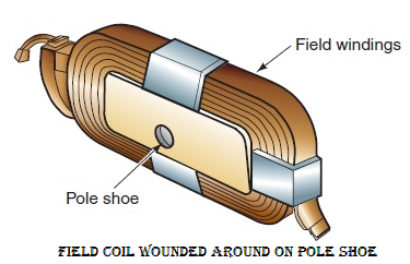
Ques 5. The function of a Pole shoe in a DC machine is
- To increase field winding Reactance
- To increase the field winding Resistance
- To decrease the field winding resistance
- Uniform distribution of flux✓
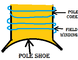
The field magnet has two parts Pole Core Pole Shoe:- Each pole core consists of a pole shoe that has a curved surface. Pole shoes are made larger than their body because the permeability of the pole body is more than that of the air gap and hence better uniform flux distribution can be obtained in the machine which reduces the flux leakage and gives better output. Hence the pole shoes spread out the flux in the air gap and reduce the reluctance of the magnetic path due to its large cross-section. The pole shoes support the exciting coils. The pole shoes are made curved to ensure a uniform air gap around the armature core. The following are the functions of pole shoes:
Ques 6. In the case of the purely inductive circuit, the current is maximum when
- Applied voltage is negative maximum
- Applied voltage is maximum
- Applied voltage is half of the maximum
- Applied voltage is zero✓
Consider a purely inductive circuit as shown in the figure. In a purely inductive circuit, the current lags the voltage by 90°. To understand this we must have to consider the relationship between applied voltage and the induced voltage. How the current and applied voltage can become 90° out of phase with each other can best be explained by comparing the relationship between the current and induced voltage. As we know that the induced voltage is proportional to the rate of change of the current (speed of cutting action). At the beginning of the waveform, the current is shown at its maximum value in the negative direction. At this time, the current is not changing, so the induced voltage is zero. As the current begins to decrease in value, the magnetic field produced by the flow of current decreases or collapses and begins to induce a voltage into the coil as it cuts through the conductors (Figure.). The greatest rate of current change occurs when the current passes from negative, through zero and begins to increase in the positive direction. Because the current is changing at the greatest rate, the induced voltage is maximum. As current approaches its peak value in the positive direction, the rate of change decreases, causing a decrease in the induced voltage. The induced voltage will again be zero when the current reaches its peak value and the magnetic field stops expanding. It can be seen that the current flowing through the inductor is leading the induced voltage by 90°. Because the induced voltage is 180° out of phase with the applied voltage, the current lags the applied voltage by 90°. Or Mathematically we can prove the same Consider the sinusoidal current and voltage waveform.As we know that the voltage leads the current the by 90°. i.e I = Imsinωt The value of current will be maximum when ωt = 90° Then I = Imsin90° V = Vmsin(180°) V = 0 Hence when the current will reach its maximum value the voltage will become zero.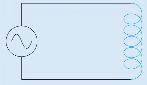
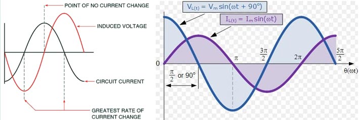
V = Vmsin(ωt + 90°)
I = Im
Ques 7. The material used for making shunts for measuring instruments is
- Indium
- Manganin✓
- Lead
- Nickle
Manganin is the trademarked name for an alloy that consists of three metallic elements – Copper, Nickel, and Manganese. The feature of manganin is that its resistivity remains constant over a wide range of temperatures. Manganin is virtual of zero temperature coefficient of resistance and so it is highly stable. Manganin is much more resistive than copper so used as a standard resistance in many measuring instruments. Manganin Composition This metal alloy consists of the following metals in the following proportions: Manganin has been used for different industrial purposes from the moment of its discovery. The properties of this material make it most efficient for certain applications. It is widely used in industries for manufacturing various substances like: The wire and foil of this material are mainly used to manufacture various resistors – mainly ammeter shunts. This metal alloy has a very low-temperature coefficient of resistance. It also has long-term stability. These properties make it very useful to be used for making shunts. Manganin is also used for series resistors (used in voltmeters), swamp resistors (to reduce thermal EMFs) etc. Note:- The manganin is used for making a shunt for dc Instrument while the Constantine is used for making the shunt of an A.C instrument.
Uses of Manganin
Shunts
Ques 8. The speed of rotating the magnetic field of a 3-φ 50 Hz induction motor running at 960 RPM will be
- 960 RPM
- 1500 RPM
- 1000 RPM✓
- 1200 RPM
We know that the synchronous speed of the rotating magnetic field produced is expressed as Ns = 120f/P Here f = 50 Hz but the number of poles of the stator winding has not been mentioned. The number of poles can be 2, 4, 6, 8 —-etc For P = 2 Ns = 120f/P = 120 x 50/2 = 3000 RPM For P = 4 Ns = 120f/P = 120 x 50/4 = 1500 RPM For P = 6 Ns = 120f/P = 120 x 50/6 = 1000 RPM For P = 8 Ns = 120f/P = 120 x 50/8 = 750 RPM We know that an induction motor runs at a speed slightly less than the synchronous speed. Here, Nr = 960 rpm (given). Synchronous speed corresponding to this rotor speed must, therefore, be 1000 rpm. Thus, Nr= 960 RPM and Ns = 1000 rpm.
Ques 9. Transformers work on the principle of
- Fleming’s Law
- Dynamic Induction
- Joule’s Law
- Faraday Law of Electromagnetic Induction✓
A transformer is a static device that converts the alternating current energy from one voltage level to another voltage level. A transformer operates on the principle of Faraday Law of electromagnetic induction i.e mutual inductance, between two coils. According to these Faraday’s laws, Mutual induction is the process by which a coil magnetically induces a voltage into another coil located in close proximity to it. Transformers get their name from the fact that they “transform” one voltage level to another voltage level. A single-phase transformer basically consists of two electrical coils of wire, one called the “Primary Winding” and another called the “Secondary Winding”.Transformer Working
“Rate of change of flux linkage with respect to time is directly proportional to the induced EMF in a conductor or coil”.
Ques 10. The thickness of stator lamination of a 3 phase induction motor, when compared to its rotor lamination is:
- Same
- Less✓
- More
- Twice
Similar to other rotating electrical machines, a three-phase induction motor also consists of two main parts: the stator and the rotor (the stator is the stationary part and the rotor is the rotating part). Apart from these two main parts, a three-phase induction motor also requires bearings, bearing covers, endplates. etc. for its assembly. The stator of a three-phase induction motor has three main parts namely, the stator frame, stator core, and stator windings. The stator frame can either be casted or can be fabricated from rolled steel plates. The stator core is built up of high silicon sheet steel laminations of thickness 0.4 to 0.5 mm. Each lamination is separated from the other by means of either varnish, paper, or oxide coating. As Stator is the stationary part of the motor. Hysteresis and eddy current losses occur in the stator, because of changing flux associated with it. Eddy’s current losses in the 3 phase induction motor is given by Eddy current losses = Ke × Bm2 × f2 × t2 Where Ke = Eddy’s current constant Hence the eddy current losses are directly proportional to the square of the thickness of stator lamination. As such, the stator is laminated and the thickness of lamination is kept at the minimum possible to reduce the eddy current loss occurring in the stator. Thus, cold-rolled steel punchings 0.5 mm thickness is generally used for the stator of 3 phase induction motor.
Bm = Maximum flux density
t = thickness of the core

