DMRC Junior Engineer Previous Year Electrical Question Paper with explanation and Solution -2015
Ques 1. Three resistances of 30 ohms, 15 ohms and 5 ohms are connected In parallel, their combined resistance will be:
Greater than 30 ohm
Between 30 to 15 ohm
Between 15 to 5 ohm
Less than 5 ohm✓
When the resistance is connected in the parallel the Equivalent resistance is always than each individual resistor.
Now in the above question, the value of minimum resistance is 5 ohm then the equivalent resistance in parallel will be always less than 5 ohms.
Ques 2. Number of diodes required in the ordinary full-wave rectifier is
1
2✓
3
4
Rectifier in a device that converts alternating current into direct current. Rectifier circuits use semiconductor diodes as rectifying elements. Following are the different types of rectifier circuits:
Half-wave rectifier
Full-wave rectifier
The full-wave rectifier can be built in the following ways:
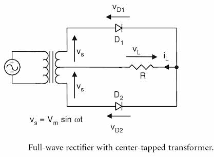
Full-wave rectifier using two diodes and a center-tapped transformer.
Full-wave bridge rectifier using four diodes and an ordinary transformer.
A step-down transformer is used to reduce the ac supply voltage to the required level. Center tapping in the secondary of the transformer is done to obtain two equal voltages but of opposite phases.
During the positive half-cycle of the ac supply, Diode D1 conducts and D2 remains off. During the negative half-cycle of the ac supply, Diode D2 conducts and D1 remains off.
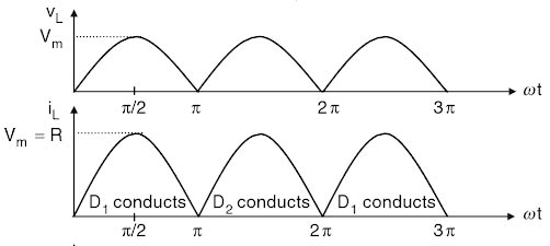
It is clear that each diode, together with the associated half of the transformer, acts as a half-wave rectifier. The outputs of the two half-wave rectifiers are combined to produce full-wave rectification in the load. As far as the transformer is concerned, the dc currents of the two halfwave rectifiers are equal and opposite, such that there is no dc current for creating a transformer core saturation problem. The voltage and current waveforms of the full-wave rectifier.
Ques 3. Two capacitors of values 12μF and 4μF ate connected in series, the capacitance or the combination is:
16μF
8μF
3μF✓
None of these
When the capacitor is connected in series there equivalent capcitance = 1/C1 + 1/C2 or C1C2/(C1 + C2)
= 12 x 4/(12 + 4) = 3μF
Ques 4. In balanced 3φ supply system current In the neutral is equal to:
Phase current
Line current
√3Phase current
Zero✓
A balanced three-phase voltage supply consists of three individual sinusoidal voltages that are all equal in magnitude and frequency but are out-of-phase with each other by exactly 120o electrical degrees. The phase voltages are all equal in magnitude but only differ in their phase angle.
The three windings of the coils are connected together at points, a1, b1 and c1 to produce a common neutral connection for the three individual phases. Then if the a2 is taken as the reference phase each individual phase voltage can be defined with respect to the common neutral as.
Then Red phase VRN = Vm sinθ Yellow Phase VYN = Vm sin(θ – 120°) Blue Phase VBN = Vm sin(θ – 240°) or VBN = Vm sin (θ + 240°)
If the red phase voltage, VRN is taken as the reference voltage so the voltage in the yellow phase lags VRN by 120°, and the voltage in the blue phase lags VYN also by 120°. But we can also say the blue phase voltage, VBN leads the red phase voltage, VRN by 120°.
As the three individual sinusoidal voltages have a fixed relationship between each other of 120o they are said to be “balanced” therefore, is a set of balanced three-phase voltages their phasor sum will always be zero as Va + Vb + Vc = 0
In a 3-phase, delta-connected system, no wire exists for the return current i.e there is no neutral point, so the phasor sum of all line currents is forced to be zero regardless of a balanced or unbalanced load. With an unbalanced 3-phase load, however, this imposed zero on the return current produces unbalanced line-to-line voltages.
Ques 5. Tesla is the unit of
MMF
Flux
Flux density✓
None
The Tesla (symbolized T) is the standard unit of magnetic flux density. It is equivalent to one weber per meter squared (1 Wb. m -2 ).
Magnetic flux density is defined as the amount of magnetic flux in an area taken perpendicular to the magnetic flux’s direction.
B = Φ/A
where,
B is magnetic flux density in teslas (T),
Φ is magnetic flux in webers (Wb), and
A is an area in square meters (m2).
Flux describes the quantity which passes through a surface or substance.
The unit of electrical flux is Volt Meter and the unit of magnetic flux is Weber.
Magnetomotive force, also known as magnetic potential, is the property of certain substances or phenomena that give rise to the magnetic field. The standard unit of magnetomotive force is the ampere-turns (AT).
Ques 6. If two supply terminals of a 3φ induction motor are interchanged, then the:
Speed of the motor will become zero
Speed of the motor will increase
Motor will continue to run in the same direction with less speed
Motor will rotate in the opposite direction✓
The direction of rotation of a 3 phase induction motor can be reversed by interchanging any two of the three motor supply lines in the stator winding. This interchange of the supply results in the direction of the rotation of the magnetic field.
The phase sequence of the three-phase voltage applied to the stator winding is A-B-C. If this sequence is changed to A-C-B, it is observed that the direction of rotation of the field is reversed i.e., the field rotates counterclockwise rather than clockwise.
This causes the currents in the phases to interchange their relative timing in going positive and negative with the result that the magnetic field produces the reversal in direction of rotation.
Ques 7. A transformer has 500 turns on its primary and 50 turns on secondary winding its transformation ratio will be:
0.001
0.1
10✓
100
Transformer ration K = N1/N2 = 500/50 = 10
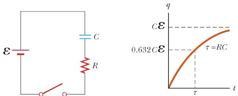
Ques 8. The time constant in an R.C. circuit is equal to
L/R
C × R2
C × R✓
0.5Q/V
Consider the series RC circuit. Considered the capacitor is initially uncharged with the switch opened. After the switch is closed, the battery begins to charge the plates of the capacitor and the charge passes through the resistor. As the capacitor is being charged, the circuit carries a changing current. Because of the presence of the resistor the capacitor is not charged all at once but gradually over time. The charging process continues until the capacitor is charged to its maximum equilibrium value, Q = Cε, where ε is the maximum voltage across the capacitor.
Once the capacitor is fully charged, the current in the circuit is zero. If we assume the capacitor is uncharged before the switch is closed, and if the switch is closed at t = 0, we find that the charge on the capacitor varies with time according to the equation
q = Q(1– e-t/RC)
The RC time constant, also called tau, the time constant (in seconds) of an RC circuit, is equal to the product of the circuit resistance (in ohms) and the circuit capacitance (in farads), i.e.
τ =RC
The time constant represents the time required for the charge to increase from zero to 63.2% of its maximum equilibrium value. This means that in a period of time equal to one time constant, the charge on the capacitor increases from zero to 0.632Q.
Now consider the circuit consisting of a capacitor with an initial charge Q. a resistor and a switch. Before the switch is closed, the potential difference between the charged capacitor is Q/C. Once the switch is closed, the charge begins to flow through the resistor from one capacitor plate to the other until the capacitor is fully discharged. If the switch is closed at t = 0, it can be shown that the charge q on the capacitor varies with time according to the equation
q = Qe-t/RC
The charge decreases exponentially with time, as shown in Active Figure 18.17b. In the interval t= τ = RC, the charge decreases from its initial value Q to 0.368Q.
Ques 9. Three-phase induction motor usually operates on
0.8 P.F leading
0.8 P.F lagging✓
Unity P.F
Very low P.F
The power factor of a 3-phase induction motor is low at no load because of air gap, and the reluctance of the magnetic circuit of the 3-phase induction motor is very high. Consequently, the current drawn by the motor on no-load is largely magnetizing. The no-load current lags the applied voltage by a large angle. For this reason, the p.f. of a lightly loaded 3-phase induction motor is very low.
A 3-phase induction motor draws a large magnetizing current because of the high reluctance of the magnetic circuit; air-gap being the main reason. When the load on the motor is increased, the in-phase current supplied to the motor increases, but the magnetizing component of the current remains the same. However, because of the large value of magnetizing current, which is present regardless of load, the p.f. of a 3-phase induction motor even at full load seldom exceeds 0.85.
Ques 10. An electric motor converts
Mechanical Energy into Electrical Energy
AC into DC
Electrical energy into mechanical Energy✓
None of these
Electric motors are devices that convert electric energy into magnetic energy and finally into mechanical energy. Electromagnetism is the basis of an electric motor operation by generating magnetic forces necessary to produce either rotational or linear motion. For rotating electric motors, it is the interaction between the stator and rotor magnetic fields that create motor torque to drive external loads.
In the motor, the current is passed through a loop that is immersed in a magnetic field. In addition, when electric current flows through a coil, it generates a magnetic field. When two magnets get close together the North and the South poles attract, whereas the same poles will repel each other. Thus, the magnetic field and coil currents produce force, and consequently a torque to rotate the rotor is generated.