Ques.51. In a 3-phase half wave rectifier, if the input phase voltage is 200 V, the PIV required for each diode will be (SSC-2017)
400 V
346 V
370 V
200 V
Answer.2. 346 V
Explanation:
Peak inverse voltage or PIV of diode = Maximum value of secondary voltage
= 200 x √3 = 346 V
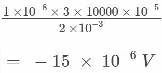
Ques.52. Hall effect transducer with hall coefficient KH = -1 x 10⁻⁸ is required to measure a magnetic field of 10,000 gauss. A 2 mm bismuth slab is used as the transducer with a current of 3A. The output voltage of the transducer will be (SSC-2017)
-15 x 10 -6 V
-7.5 x 10 -6 V
10 x 10 -6 V
-22.5 x 10 -6 V
Answer.1. -15 x 10 -6 V
Explanation:
Hall effect Output Voltage
= EH = KH IB / T
Where I is current
T is Thickness
B = Magnetic field = 10000 gauss = 10000 x 10-5 Wb/m2
Ques.53.For power measurement of the three-phase circuit by two wattmeter method, when the value of the power factor is less than 0.5 lagging. (SSC-2017)
One of the wattmeters will read zero
Both give the same reading
One of the wattmeter connections will have to be reversed
Pressure coil of the wattmeter will become ineffective.
Answer.3. One of the wattmeter connections will have to be reversed
Explanation:
Some point must be noted for two wattmeter method! READ THE POINT CAREFULLY
If phase angle Φ = 0°, the readings of the two wattmeters are equal.
If phase angle Φ < 60°, the readings of both the wattmeters are positive and the total power is the sum.
If phase angle Φ = 60°, the reading P2 of the wattmeter W3 is zero.
If phase angle Φ> 60°, i.e., if the power factor of the load is less than 0.5, the reading of wattmeter W2 is negative. In such a case, the connection of either the current coil or the potential coil has to be reversed so that the pointer may deflect in a positive direction. The reading obtains after the reversal of the coil should then be taken as negative while calculating the power factor or the total power.
Now in the above question, the value of the power factor is less than 0., therefore, one of the wattmeter connections will have to be reversed.
Ques.54.In two wattmeter method of measuring 3-phase power, power factor is 0.5, then one of these wattmeters will read (SSC-2017)
W/2
Zero
√2 W
W/√2
Answer.2. Zero
Explanation:
Power factor = cos Φ = 0.5
Φ = 60°
In question number 8 and point number 3 “If phase angle Φ = 60°, the reading P2 of the wattmeter W2 is zero”.
Ques.55. A CRT has a deflection factor of 18 V/cm. The amount of deflection seen on the screen for deflection voltages of 54V is (SSC-2017)
3 cm
18 cm
54 cm
0.056 cm
Answer.1. 3cm
Explanation:
Deflection sensitivity and Deflection Factor in CRT
Deflection sensitivity is given as
S = D / Vd
Where D= amount of deflection
Vd = anode voltage
Similarly, Deflection factor is given as
G = 1/S
Therefore amount of Deflection “D” will be
D = Vd / G
= 54/18 = 3 cm
Ques.56. A 0-10 mA PMMC ammeter reads 4 mA in a circuit. Its bottom control spring snaps suddenly. The meter will now read nearly (SSC-2017)
10 mA
8 mA
2 mA
Zero
Answer.4. Zero
Explanation:
The spring gives controlling torque and is connected in series with the coil. If spring is snapped, there will be no deflection. Hence the pointer will come in its initial position i.e zero.
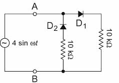
Ques 53. A voltage source VAB = 4 sin ωt is applied to the terminal A and B of the circuit shown in the given figure. The diodes are assumed to be ideal. The impedance offered by the circuit across the terminal A and B is (SSC-2017)
5 kΩ
10 kΩ
15 kΩ
20 kΩ
Answer.2. 10 KΩ
Explanation:
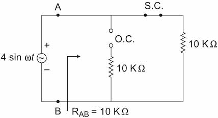
In the first half of the cycle, Diode D1 conducts and the impedance offered will be 10 KΩ as shown in the below figure
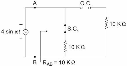
In the negative half cycle, diode D2 conducts and impedance offer will be 10 KΩ
Hence equivalent impedance offered across terminal A and B is 10 KΩ.
Ques.54. The percentage of limiting error in the case of an instrument reading 0f 8.3 V with a 0 to 150V voltmeter having a guaranteed accuracy of 1% full-scale reading is (SSC-2017)
1.810%
0.181%
18.10%
0.0018%
Answer.3. 18.10%
Explanation:
Limiting Error = accuracy * full-scale reading
= (1 x 150) / 100 = 1.5 V
% limiting error when measuring 8.3 V
% error=(maximum error/scale reading) * 100
= (1.5 x 100) / 8.3
= 18.10 %
Ques.55. The dead time of an instrument refers to (SSC-2016 Set-1)
The large change of input quantity for which there is no output.
The time encountered when the instrument has to wait for some reactions to take place
Retardation or delay in the response of an instrument to a change in the input signal
The dead time of an instrument is equal to zero.
Answer.3. Retardation or delay in the response of an instrument to a change in the input signal
Explanation:-
Dead-time of Instrument:- A time during which a new signal or variation in a signal cannot be detected due to some physical characteristics of the system or the transducers is known as dead time.
In any control system with feedback, the system cannot respond instantly to any change and thus there are delays while the system takes time to accommodate the change. Such delays are referred to as dead time or Ings. For example, in the control of the temperature in a room by means of a central heating system, if a window is suddenly opened and the temperature drops or the thermostat is suddenly set to a new value, a lag will occur before the control system responds, switches on the heater and gets the temperature back to its set value.
Ques.56. Strain gauge rosettes are used when _________ (SSC-2016 Set-1)
The direction of hoop stress is not known
The direction of principal stress is known
The direction of principal stress is not known
The direction of longitudinal stress is not known
Answer.3. The direction of principal stress is not known
Explanation:-
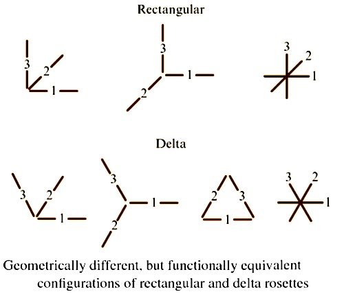
Strain-Gauge Rosettes
A strain-gauge rosette is, by definition, an arrangement of two or more closely positioned gage grids, separately oriented so as to measure the strains along with different directions in the underlying surface of a test part.
Rosettes are designed to serve a very practical purpose in experimental stress analysis. It can be shown that for the not uncommon case of the general biaxial stress state, with the principal directions unknown, three independent strain measurements (in different directions) are required to determine the principal strains and stresses. Even when the principal directions are known in advance, two independent strain measurements are needed to obtain principal strains and stresses.
For the purpose of meeting these requirements, strain-gage manufacturers typically offer three basic types of strain gage rosettes, each in a variety of forms:
Tee – two perpendicular grids
Rectangular- three grids, with the second and third grids angularly displaced from the first grid by 45 and 90°, respectively
Delta – three grids, with the second and third grids 60 and 120° away, respectively, from the first grid
As illustrated in Fig. , rectangular and delta rosettes may appear in any of several geometrical different, but functionally equivalent, forms.
When the directions of the principal strains are unknown, a three-element rectangular or delta rosette is required, and the rosette can be installed without regard to orientation. Functionally, there is little difference between the rectangular and delta rosettes. Because the gage axes in the delta rosette have the maximum possible uniform angular separation (effectively 120°), this rosette is assumed to yield the optimum sampling of the underlying strain distribution.
Ques.57. The series magnet of a single-phase Energy meter consists of the coil of _____. (SSC-2016 Set-1)
Thin wire of few turns
Thin wire of more turns
Thick wire of few turns
Thick wire of more turns
Answer.3. Thick wire of few turns
Explanation:-
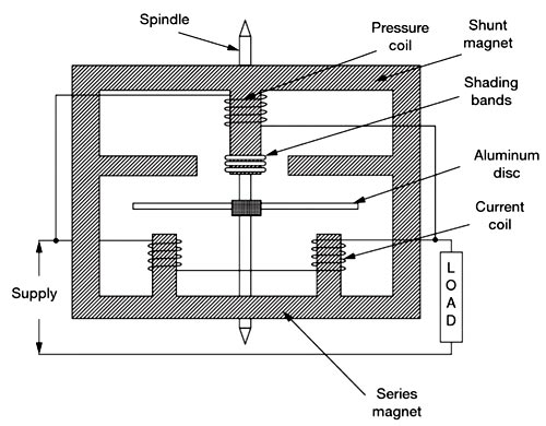
Induction-type Single-phase Energy Meter
An induction-type instrument can be used as an ammeter, voltmeter, or wattmeter, the induction-type energy meters are more popular. Induction-type single-phase energy meter is used invariably to measure the energy consumed in an AC circuit in a prescribed period where supply voltage and frequency are constant. The energy meter is an integrating instrument that measures the total quantity of electrical energy supplied to the circuit in a given period.
A single-phase energy meter has four essential parts:
Operating system
Moving system
Braking system
Registering system
Operating System
The operating system consists of two electromagnets. The cores of these electromagnets are made of silicon steel laminations. The coils of one of these electromagnets (series magnet) are connected in series with the load and are called the current coil. The Current coil consists of few turns of thick wire, connected in series with the load. It carries full load current which depends upon the angle of lag or lead of the load. Therefore the currents in the pressure coil and current coil have a phase difference of nearly 90 degrees.
The other electromagnet (shunt magnet) is wound with a coil that is connected across the supply, called the pressure coil. The voltage coil consists of many turns of fine wire encased in plastic, connected in parallel with the load and is highly inductive. This coil is connected in parallel with the supply or load and carries the current proportional to voltage. The current in this coil lags behind the voltage approximately by 90 degrees. The pressure coil, thus, carries a current that is proportional to supply voltage.
Shading bands made of copper are provided on the central limb of the shunt magnet. Shading band as will be described later, are used to bring the flux produced by a shunt magnet exactly in quadrature with the applied voltage.
The two field fluxes produced by the pressure coil and current coil act on the aluminum disc, induce eddy currents in the disc, and hence the disc rotates due to the interaction of the two fluxes developed. The speed of the disc is proportional to the product of voltage, current and the number of revolutions of the disc (i.e. time). In other words, the disc speed is proportional to the energy consumed by the load. The number of revolutions completed by the disc for one kilowatts hour is called meter constant.
Ques.58. Unbonded strain gauges are _____. (SSC-2016 Set-1)
Exclusively used for stress analysis
Exclusively used for transducer applications
Used for unbounded strains only
None of these
Answer.2. Exclusively used for transducer applications
Explanation:-
The strain is defined as the deformation of materials caused by the action of stress. A body subjected to external forces is in the condition of both stress and strain. Stress cannot be measured directly. As there is a relationship between stress and strain, the effect of stress can be shown by measurement of the strain. Thus, the stress occurring in a body can be computed if sufficient strain information is available. The measurement helps in knowing better about any structure, whether it is strong enough for the purpose or it may fail in use.
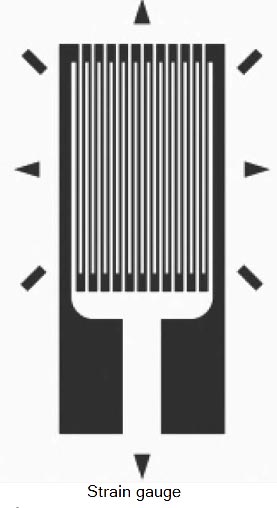
Measurement of Strain Using Electrical Resistance Strain Gauges
Strain gauges are made up of a long, thin strip of conductive material arranged in a zigzag manner. Load cells typically contain multiple strain gauges aligned and wired in a Wheatstone bridge circuit. When stress is applied to a strain gauge, the resistance of the strain gauge changes and unbalances the Wheatstone bridge, resulting in a signal output (voltage) that is proportional to the stress.
When a strain gauge is expanded or contracted by an external force, it experiences a change in electrical resistance. By bonding a strain gauge to the surface of a test specimen with an electrical insulator between them, the strain gauge changes dimension according to the expansion or contraction of the test specimen, resulting, in a change in resistance. This resistance is measured using the Wheatstone bridge which is the indication of the strain of the specimen at that point.
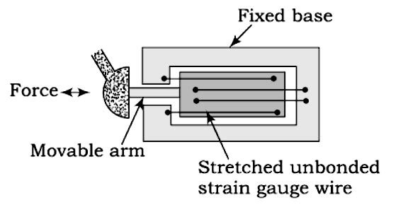
Types of Strain Gauges There are basically two types of strain gauges unbonded and bonded.
Unbonded Resistance Strain Gauge: In general, the basic usage of the unbonded strain gauge is a displacement transducer. It can be constructed in a variety of configurations. The unbonded resistance strain gauge uses a strain sensitive wire (or wires) with one end fixed and the other end attached to a movable element. Strain, induced on the wire by the displacement of the movable element, produces a change in resistance proportional to the displacement of the movable element. The unbonded strain gauge can measure the very small motion of the order of 50, μm and very small forces. The device is less robust than the bonded gauge and was developed at a time when the bounding technique was not reliable. With the advancement of improved bonding cement, unbonded wire strain gauges have become less common.
2. Bonded Resistance Strain Gauge: Bonded resistance strain gauge can be grouped into those that require an adhesive to fix the gauge so the pressure-sensing element (metal foil and strain sensitive wires) and those attached to the strain-sensing element by techniques that effectively make the strain gauge an integral part of the strain-sensing element (thin film and semiconductor).
Ques.59. The voltage of a circuit is measured by a voltmeter having input impedance comparable with the output impedance of the circuit thereby causing an error in voltage measurement. This error may be called as (SSC-2016 Set-1)
Gross Error
Random Error
The error caused by the loading effect
The error caused by misuse of the instrument
Answer.3. The error caused by the loading effect
Explanation:-
Loading Effects: Loading effect due to an improper way of using the instrument cause serious errors. The best example of such a loading effect error is connecting a well-calibrated voltmeter across the two points of high resistance circuit. The same voltmeter connected in a low resistance circuit gives an accurate reading. Thus, the errors due to the loading effect can be avoided by using an instrument intelligently and correctly.
Ques.60. What should be the size of the slide wire of the potentiometer to make it to achieve high accuracy? (SSC-2016 Set-1)
As long as possible
As short as possible
1 meter
Neither too thin nor too thick
Answer.1. As long as possible
Explanation:-
A potentiometer is an instrument designed to measure an unknown voltage by comparing it with a known voltage. This known voltage is supplied by a standard cell or through a reference source. The potentiometer makes use of a null or balanced condition for the purpose of measurement.
The potential difference across a length of the potentiometer wire is directly proportional to its Length (or) when a steady current is passed through a uniform wire, potential drop per unit length or potential gradient is constant.
E ∝ L ⇒ E = φL
Where φ is the potential gradient
So In the case of longer wire, the fall of potential per unit length is small. In other words, the potential gradient is small. Lesser the potential gradient, more accurate is the potentiometer.