Ques.51. Which of the following is used for the measurement of the insulation resistance?
- Megger
- Wattmeter
- Ammeter
- Voltmeter
Answer.1. Megger Explanation:- Testing of Insulation Resistance of Complete Installation to Earth The principal purpose of testing the insulation is to verify that there are no inadvertent connections between live conductors and between live and Earth before the installation is energized. Tests are required between live conductors (e.g. between phases and between phase(s) and neutral) and between all live conductors and Earth. Insulation resistance of the installation depends on many factors such as atmospheric conditions, humidity, dirt, etc. As such its calculation is not possible, but it can be readily measured. Normally the insulation resistance is quite high and can be measured by an instrument called “megger” usually used for the measurement of high resistance. The main object in performing this test is to ascertain whether the complete wiring is sound enough to avoid leakage current. As per the Indian electricity rules, the leakage current of installation should not exceed 1/5000 of the maximum supply-demand of the consumer. As such the insulation resistance of the complete installation to earth should not be less than 1 MΩ. Insulation resistance test must be conducted on dc voltage of value not less than twice the standard supply voltage. However, they need not exceed 500 V for medium voltage circuits. (ii) The main fuse to be taken out. (iii) All other fuses to be provided. (iv) All lamps must be put in the on position. (v) All switches must be made on. (vi) Live and neutral wire to be shorted together. Testing of Insulation Resistance Between Conductors After testing the insulation resistance of installation to earth, the insulation resistance between line and neutral should be measured. The major object in conducting this test is again to ensure that the insulation is quite sound between the conductors and there are no chances of any appreciable leakage current between them. This test should be carried out under the following conditions of installation (i) The Main switch is off. (ii) The main fuse has withdrawn. (iii) All other fuses in their position. (iv) All switches in on position. (v) All lamps from the holders were removed. (vi)Two terminals of the meager are connected to the line and neutral wire. Insulation resistance measured under the above condition by a megger should not be less than 50 MΩ divided by the number of outlets(points + switches). However, it need not be more than 1 MΩ.
Insulation resistance of the installation to earth is measured by a megger generating dc voltage of about 500 V. Insulation resistance is measured under the following conditions.
(i) Main switch in off position.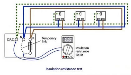
Ques.52. The interaction between a transmission line and the communication line is minimized by
- Transposing transmission as well as communication lines
- Increasing the height of the transmission line tower
- Increasing the distance between the two lines
- All of the above
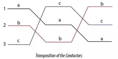
Answer.4. All of the above Explanation:- In practice, it is observed that the power lines and the communication lines run along the same path. Sometimes it can also be seen that both these lines run on Sam supports along the same route. The transmission lines transmit bulk power with relatively high voltage. Electromagnetic and electrostatic fields are produced by these lines having sufficient magnitude. Because of these fields, voltages, and currents at induced in the neighboring communication lines. Thus it gives rise to interference c power line with communication circuit. “if the power line is running along the same route as the communication line, there will be interference in Steps for Reducing Telephone interference Transposition:- Transposition of overhead line conductors refers to exchanging the positions of power conductors at regular intervals along the line so that each conductor occupies the original position of every other conductor over an equal distance in order to reduce crosstalk and otherwise improve transmission. Usually, telecommunication lines and power lines travel close to each other, then the current flowing through the power line produces magnetic flux linkage between telecommunication line so that voltage is induced in the telecommunication lines which causes disturbance in communication. This phenomenon is called radio interference which is suppressed by the transpose of the power line. The transposition arrangement of the conductor can simply show in the following figure. The conductor in Position 1, Position 2 and Position 3 changes in a specific arrangement to reduce the effect of capacitance and the electrostatic unbalanced voltages. Effect of Transposition:- The purpose of transposition is to balance the capacitances of the line so that the electrostatically induced voltages balance out in the length of a complete set of transposition, and this length is called a barrel. Transposition also results in the decrease of electromagnetically induced e.m.f. on the wires, because of fluxes due to the positive and negative phase sequence, currents will add up to zero along the barrel. This flux due to the zero-phase sequence or longitudinal current is unaffected by transpositions of power systems because it flows along the three conductors in parallel. To reduce the e.m.f. in the telephone line due to its zero phase sequence currents the telephone line is transposed by proper coordination of transpositions of the power and communication lines. The induced voltage can be reduced to very small proportions under normal working conditions.Interference of Transmission and communication line
the communication line due to both electromagnetic and electrostatic effects.” The electromagnetic effect produces currents, which are superimposed on the communication signal, and thereby it is distorted. However, the electrostatic effect induces a voltage in the communication line, which may be dangerous in handling the telephone receiver.
Ques.53. In order to switch-off and EHV circuit for maintenance, the following sequence is adopted:
- Open the circuit breaker, open the isolator, operate the earth switch
- Operate the earth switch, open the isolator, open the circuit breaker
- Open the isolator, operate the earth switch, open the circuit breaker
- Open the isolator, open the circuit breaker, operate the earth switch
Answer.1. Open the circuit breaker, open the isolator, operate the earth switch Explanation:- Switching sequence – to turn on or off a bus bar, equipment, power plant requires proper steps and skill. A single mistake would cause an accident. Step 1: Open the circuit breaker: CB is a device that can make and break the circuit under normal as well as under faulty conditions manually or automatically. Step 2: Open the isolator: Isolator is a device that always operates under no-load condition. This is because it has no provision for arc quenching. Its function is to isolate the circuit after operation of the circuit breaker and discharge the grapes charges to earth through the earth switch. Step 3: Operate the Earth switch: After opening the circuit breaker and manually disconnecting the isolator the next is to engage the earth switch. Its function is to discharge any remnant charge due to residual magnetism which might be lethal to humans and expensive testing equipment.
Ques.54. Which of the following statements is incorrect?
- Station batteries are used to operate relay only
- The lightning arresters have basically surged diverters
- An impedance relay has maximum fault current when the fault occurs near the relay
- A high-speed relay has an operation of 1 to 2 cycles
Answer.2. The lightning arresters have basically surged diverters
Explanation:-
Surge Absorber
The steepness of the wavefront of travailing waves can cause damage to the apparatus in addition to the magnitude of the wave. The steeper is the traveling wave, the more damage to the apparatus is more. Thus to reduce the steepness of the wavefront of the surge, a surge absorber is used.
The surge absorber is a protective device that can reduce the steepness of the wavefront of a surge and absorbs energy contained in travailing waves. Though the surge diverter and surge absorber eliminate the surge, the way in which it is done is different in the two devices. The surge diverter diverts the surge to the earth while the surge absorber absorbs energy contained in the surge.
The capacitor is used as a surge absorber. XC = 1/2πfC, for high frequency, it offers low reactance. A surge is a high-frequency wave, the capacitor acts as a short circuit device, passing it to earth.
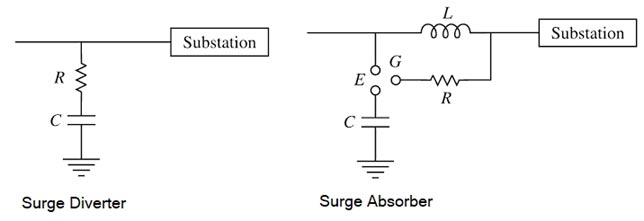
In another type of surge absorber, the parallel combination of resistor and inductor is used as a surge absorber. This combination is placed in series with the line steep wavefronts. Since XL = 2πfL, the inductor offers high resistance at high frequencies. The surge then flows through the resistor, where it is dissipated.
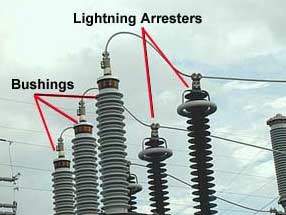
Surge arresters are also called lightning arresters. They are applied to electrical systems to protect equipment such as transformers, rotating machines, etc., against the effects of overvoltages resulting from lightning, switching surges, or other disturbances. Surge arresters are also connected in shunt with equipment to be protected. It has basically a nonlinear resistor so that its resistance decreases rapidly as the voltage across it rises.
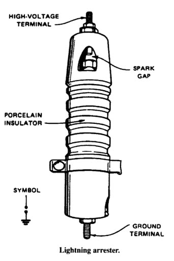
After the surge ends and the voltage across the arrester returns to the normal 50 Hz line-to-neutral voltage level, the resistance becomes high enough to limit the arc current to a value that can be quenched by the series gap of the arrester. Therefore, the surge arrester provides both gap protection and nonlinear resistance. A disruptive discharge between the electrodes of a surge arrester is called sparkover. The highest value of the applied voltage at which an arrester will not flash is the withstand voltage. Current that flows through an arrester, caused by the 50 Hz system voltage across it, during and after the flow of surge current is called^follow current. Surge arresters, with their controlled breakdown characteristics, sparkover at voltages well below the withstand strength of system insulation.
Ques.55. Discrimination between main and backup protection is provided by the use of relays
- Facts
- Sensitive
- Slow
- None of the above
Answer.3. Slow Explanation:- Protection Zones The general philosophy for the use of relays is to divide the system into separate zones, which can be individually protected and disconnected on the occurrence of a fault, in order to permit the rest of the system to continue in service wherever possible. In general, a power system can be divided into protection zones – generators, transformers, groups of generator transformers, motors, busbars, and lines. It should be noted that the zones overlap at some points indicating that, if a fault occurs in these overlap areas, more than one set of protection relays should operate. The overlap is obtained by connecting the protection relays to the appropriate current transformers as illustrated in Figure. Primary protection Primary protection should operate every time an element detects a fault on the power system. The protection element covers one or more components of the power system, such as electrical machines, lines, and busbars. It is possible for a power system component to have various primary protection devices. However, this does not imply that they all have to operate for the same fault, and it should be noted that the primary protection for one item of system equipment might not necessarily be installed at the same location as the system equipment; in some cases, it can be sited in an adjacent substation. Backup protection Back-up protection is installed to operate when, for whatever reason, the primary protection does not work. To achieve this, the backup protection relay has a sensing element that may or may not be similar to the primary protection, but which also includes a time-delay facility to slow down the operation of the relay so as to allow time for the primary protection to operate first. One relay can provide backup protection simultaneously to different pieces of system equipment. Equally the same equipment can have a number of different backup protection relays and it is quite common for a relay to act as the primary protection for one piece of equipment and as backup for another.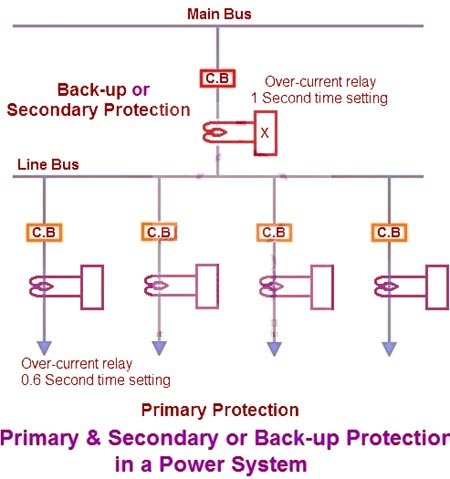
Ques.56. Induction cup relay is operated due to changes in
- Current
- Voltage
- Both 1 & 2
- None of the above
Answer.3. Both 1 & 2 Explanation:- The schematic arrangement of an induction cup structure is shown in Fig. It closely resembles an induction motor except for rotor iron is stationary, only the rotor conductor portion being free to rotate. The moving iron is a hollow metal cylinder or cup, which turns on its axis. A stationary iron core is placed inside the rotating cup to decrease the air gap without increasing inertia. The spindle of the cup carries an arm that closes contacts. A spring is employed to provide a resetting torque. When two actuating quantities are applied, one may produce an operating torque while the other may produce restraining torque. Brake magnets are not used with induction cup-type relays. The induction cup unit is a four-pole field structure with a very thin aluminum induction cup, which carries the movable contact. The opposite pole pairs are fed with any combination of voltage/voltage, voltage/current or current/current. Two pairs of coils produce a rotating field which induces the current in the rotor. Torque is produced due to the interaction between the rotating flux and the induced current, which causes rotation. The inertia of the cup is much less than that of a disc. The magnetic system is more efficient and hence the magnetic leakage in the magnetic circuit is minimized. This type of magnetic system also reduces the resistance of the induced current path in the rotor. Due to the low weight of the rotor and efficient magnetic system its torque per VA is about three times that of an induction disc type construction. Thus, its VA burden is greatly reduced. It possesses high sensitivity, high speed and produces a steady non-vibrating torque. Its parasitic torques due to current or voltage alone are small. Its operating time is in the order of 0.01 seconds. Thus with its high torque/inertia ratio, it is quite suitable for higher speeds of operation. This type of structure is more efficient torque produced than either the shaded-pole or the watt-hour structure.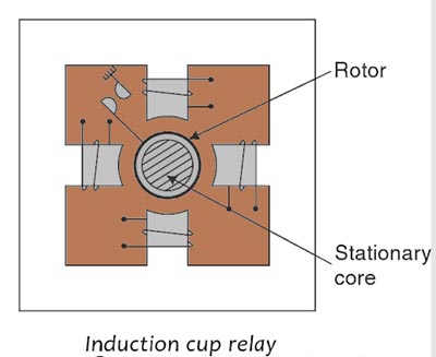
Ques.57. A.C. network analyzer is used to solve problems of
- Load flow
- Load flow and short-circuit
- Load flow and stability
- Load flow, short-circuit and stability
Answer.4. Load flow, short-circuit and stability Explanation:- In the early days, there used to be small power stations for each locality such as urban power systems. But with the growth in the demand for electricity for different purposes such as industrial, agricultural, commercial and domestic together with the guarantee regarding continuity of supply to the different consumers, has forced the power system engineers to develop grid systems which are the interconnections of different generating stations located at different places. Thus the power system of today is a complex network consisting of several sub-networks such as generation sub-networks, transmission sub-networks, and distribution sub-networks. Planning the operation of such systems under existing conditions as well as its improvements and future expansion requires load flow i.e., planning studies, short circuit studies i.e., fault analysis, and stability studies. The load flow studies are very important for planning the future expansion of the power system as well as determining its best-operating conditions. The information usually obtained from the load flow studies are the magnitude and phase angle of voltages at each bus and active and reactive power flow in each line i.e., in each element of the power system networks. The short circuit studies i.e., fault calculations and stability studies (both transient state and dynamic stability studies) are important in designing the adequate protective schemes of the electrical power system. The mathematical formulation of the power system problems for these studies viz. load flow, short circuit, and stability studies are a set of nonlinear algebraic and or differential equations, which require extensive calculations, and in most cases, these cannot be solved by hand computation. And therefore, extensive calculations required for these studies led to the design of the special purpose analog computer, called a.c. network analyzer sometimes in the year 1929. These AC network analyzers for calculating boards) differed from the DC network analyzers in that the resistance components were replaced by a combination of resistance, capacitance, and inductance components. This had the advantage that the phase relationships between the voltages and currents in different parts of the electric power distribution network could be represented directly. To keep costs down, passive components were generally used wherever possible. However, if a particular aspect of a system could not be satisfactorily represented by passive (i.e. resistance, capacitance, inductance) components, then transformers and amplifier circuits were also employed.
Ques.58. Lightning arrester connected in a power system protect electrical equipment from
- Over-voltage due to indirect lightning stroke
- Direct stroke of lightning
- Frequency fluctuation
- Overcurrent due to indirect lightning stroke
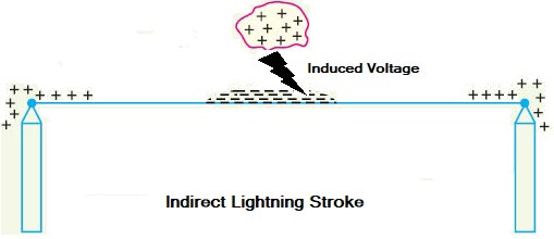
Answer.4. Over-voltage due to indirect lightning stroke Explanation:- Types of Lightning Strokes There are two main types of lightning strokes that appear on various equipment in the power system. They are viz. Direct Stroke and Indirect Stroke. Direct stroke may appear on line conductor, on tower top or on the ground wire indirect stroke may appear on overhead line conductors. Direct Stroke on Overhead Conductors These strokes are most dangerous as their effects are most severe and harmful. In this type of stroke, the discharge or the current path is directly from the cloud to the overhead line. From the line, the current path may be over the insulators down the pole to the ground. The voltage set up is in millions which can cause flashover and puncture of insulators. The insulators may get shattered till the surge is sufficiently dissipated and it travels to both sides. The wave may reach to the substation and damage the equipment because of excessive stress produced. The earthing screen and the ground wire provide protection against direct lightning strokes but do not provide any protection against travailing waves which may reach the electrical apparatus. The lightning arresters or the surge arresters are the ones who provide protection against the travailing waves. Indirect Strokes The effect of indirect strokes is similar to that of direct strokes. Their effect is more severe in the case of distribution lines than in the case of high voltage lines. These strokes are due to electrostatically induced charges on the conductors due to the presence of charged clouds. Sometimes currents may be induced electromagnetically due to lightning discharge in the immediate vicinity of the line which results in an indirect stroke. Lightning Arrester A lightning arrester is a device used in electrical power systems and telecommunications systems to protect the insulation and conductors of the system from the damaging effects of indirect lightning stroke. The arrester provides a low-impedance path to the ground for the current from a lightning strike or transient voltage and then restores to normal operating conditions. Lightning arresters are two-terminal devices in which one terminal is connected to the power line, and the other is connected to the ground. The path from line to ground is of high resistance that it is normally open. However, when lightning, which is a very high voltage, strikes a power line, it causes conduction from line to ground. Thus, voltage surges are conducted to the ground before flashover between the lines occurs. After the lightning surge has been conducted to the ground, the valve assembly then causes the lightning arrester to become nonconductive once The lightning arrester should have the following characteristics: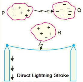
more.
Ques.59. Short-circuit currents are due to
- Single-phase to ground faults
- Phase to phase faults
- Two-phase to ground faults
- Three-phase faults
- Any of these
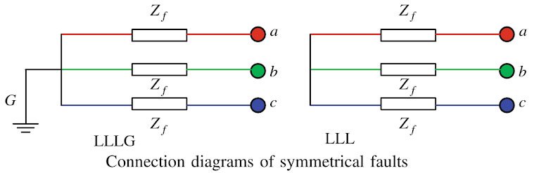
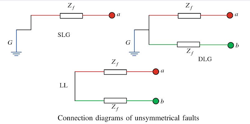
Answer.5. Any of these Explanation:- Power system equipment is required to work under unpredictable conditions, such as with a live conductor touching the ground (the short circuit problem) or lightning striking the conductors (the over voyage problem). Unter faulty conditions of the system healthy phase voltages may rise beyond the rated value, the faulty phase current may increase abnormally or both these anomalies may occur concurrently. These are undesirable effects that may lead to damage of costly equipment due to the breakdown of insulation. A short circuit occurs when two points at different potentials are connected either with zero resistance (a dead short circuit) or with a substance of low resistance (a simple short circuit). A short-circuit current is several times higher than the rated current of the equipment. In a short circuit, heavy current flows through all parts of the system into the defective area or fault. This problem is of particular significance in the present-day inter-connected power systems. A fault may be designated either as a series or a shunt fault. While a series fault is due to the breakage of conductors, a shunt fault arises due to a short circuit. Shunt faults are more serious than series faults, and many times sedes faults are converted to shunt faults. The excess MVA at the location of a fault is referred to as the fault level at that point. Calculation of short-circuit currents gain importance in the design of protective switchgear like isolators, circuit breakers, short circuit current limiting reactors, and the design of settings for protective relays. Faults are divided into two types: Symmetrical Fault The symmetrical faults are often known as balanced faults. Balanced faults occur infrequently, but they are serious due to heavy fault levels. During these faulty conditions, symmetry (or balanced condition) may be observed in all three phases. In the case of balanced faults, all three transmission lines are affected equally, and the system remains in the balanced condition. These types of faults are rare in the power system, and it contributes 2 % to 5 % of the total fault. These faults are easy to analyze. The symmetrical faults are classified as three lines to ground fault (LLLG) and three lines fault (LLL). The connection diagrams of symmetrical faults are shown in Fig. If the fault impedance, Zf= 0, then the fault is known as a solid or bolted fault. Due to symmetry, knowledge of the condition of one phase in a three-phase system is sufficient to estimate the condition of other phases. This simplifies short circuit calculations to a great extent as calculations are made on a single-phase, rather than on a 3-phase basis. Unsymmetrical Faults The faults in the power system network which disturb the balanced condition of the network are known as unsymmetrical faults. The unsymmetrical faults are classified as the single line to ground faults (SLG), double line to ground faults (DLG 10%), and line to line faults (LL 15%). More than 90 % of faults that occur in a power system are single line to ground faults. The connection diagrams of different types of unsymmetrical faults are shown in Fig. Short-circuits result from symmetrical (three-phase) faults, as well as unsymmetrical (LG, LL, LLG) faults. The occurrence of symmetrical fault brings the power transfer across the line to zero immediately, whereas the impact is only partial in case of unsymmetrical faults. The short-circuit currents may attain such high values that, if allowed to persist, they may result in thermal damage to the equipment. Therefore, the faulty section should be isolated as quickly as possible. Most of the short-circuit do not cause permanent damage. Short-circuit Fault
Types of Fault:-
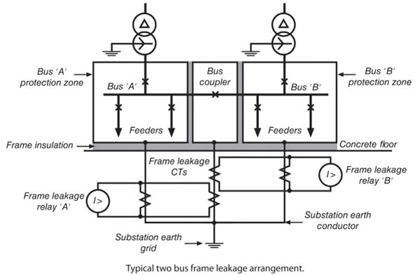
Ques.60. In busbar protection what is the method of providing an earthed metal barrier surrounding a bus throughout its length called?
- Fault bus protection
- Time graded Overcurrent protection
- Distance protection
- Differential protection
Answer.1. Fault bus protection Explanation:- The design of such a station in which the faults that develop are mostly earth faults is feasible by providing an earthed metal barrier (known as fault bus) surrounding each conductor throughout its length in the bus structure. In such an arrangement every fault that might occur must involve a connection between a conductor and an earthed metal. The faults can be detected and located by directing the flow of earth-fault current. Such a scheme of protection is called fault bus protection. It is one of the most simple forms of protection and is applicable to small size metal-clad switchgear. It is more favored for indoor and outdoor installation. This is applicable to metal-clad type switchgear installations, The framework is insulated from the ground. The insulation is light, anything over 10 ohms is acceptable. This scheme is most effective in the case of isolated-phase construction type switchgear installation in which all faults involve ground. To avoid the undesired operation of the relay due to spurious currents, a check relay energized from a C.T. connected in the neutral of the system is employed. An instantaneous overcurrent relay is used in the frame leakage protection scheme if a neutral check relay is incorporated. If a neutral check relay is not employed, an inverse time delay relay should be used.Fault Bus Protection