
Ques.31. Ionization in the circuit breaker is facilitated by
- High temperature
- The increase of mean free path
- Increasing field strength
- All of the above
Answer.4. All of the above Explanation:- Ionization of gas in circuit breaker depends upon Temperature: At high temperatures, the kinetic energy of gaseous particles increases, and energy transfer through collisions cause thermal dissociation and/or thermal ionization. The rate of thermal dissociation or ionization of a particle (molecule or atom) into several particles (atoms, ions, or electrons) is theoretically given as a function of temperature; that is, the thermal dissociation or ionization equilibrium is determined by an equilibrium coefficient that increases considerably with temperature. Electric Field Strength:- The basic phenomenon of ally discharge. including a spark. is tl~e ionization of gas atoms and molecules by electron impact. The ionization rate depends dramatically on the electric field strength, so it is only in sufficiently strong fields that the rate may become high enough to produce a plasma. The quantitative criterion for sufficiently strong fields’ varies with the gas am other conditions. Mean Free Path:- In physics, the mean free path is the average distance traveled by a moving particle (such as an atom, a molecule, a photon) between successive impacts (collisions). As the pressure is reduced, and the mean free path increases, the energy gained by an electron from the applied field increases, and the effective electron temperature rises. The energy gained is proportional to the product of the mean free path and the applied field strength E, and since the mean free path is inversely proportional to the pressure p it follows that the conditions are a function of E/p. At low values of E/p, the energy gained by an electron between collisions is small, and it makes only elastic collisions with the gas molecules, but at high values of E/p the mean electron temperature rises and the number of electrons in the high energy tail of the energy distribution increases rapidly.
Ques.32. The rated voltage of the circuit breaker is
- RMS Phase to Phase Voltage
- Average Phase to Phase Voltage
- RMS Ground to phase voltage
- RMS Phase to Phase Voltage
Answer.1. RMS Phase to Phase Voltage Explanation:- Rated Voltage of circuit breaker:- During normal operating conditions the voltage at any point of the power system is not constant. Due to this, the manufacturer guarantees perfect operation of the circuit breaker at the rated maximum voltage, which as a rule is higher than the rated nominal voltage. The rated voltage of the circuit breaker depends upon its insulation system. For below 400 kV systems, the circuit breaker is designed to withstand 10% above the normal system voltage. For an above or equal 400 kV system the insulation of the circuit breaker should be capable of withstanding 5% above the normal system voltage The rated maximum voltage of a circuit breaker is the highest RMS voltage, above nominal system voltage, for which the circuit breaker is designed and is the upper limit for operation. or The rated maximum voltage of the circuit breaker is the highest RMS phase-to-phase voltage for which the circuit breaker is designed, and is the upper limit for operation.
Ques.33. A relay used on short transmission lines is
- Reactance Relay
- Mho’s Relay
- Impedance Relay
- None of these
Answer.1. Reactance Relay Explanation:- Note:- In the case of short lines, power surges remain for a shorter period, and hence, their effect is unimportant. The predominant factor is, therefore, the effect of arc resistance. The effect of power surges stays for a longer period in the case of long lines and hence, a relay that is least affected by power surges is preferred for the protection of long lines. The MHO unit is less affected by power surges than the impedance and reactance relays and hence, it is best suited for the protection of long lines against phase
Ques.34. The time interval which is passed in between the energization of the trip coil to the instant of contact separation is called the _________
- Opening Time
- Closing Time
- Delayed Time
- None of the above
Answer.1. Opening Time Explanation:- Opening Time:- The time interval which is passed in between the energization of the trip coil to the instant of contact separation is called the opening time. It is dependent on the fault’s current level.
Ques.35. Shunt capacitance is neglected while considering
- Short transmission line
- Medium transmission line
- Long transmission line
- Medium and long transmission lines
Answer.1. Short transmission line Explanation:- Short Transmission Line: If the length of the transmission line is about 50 km and the line voltage is less than 20 kV, the line is known as the short transmission line. The effect of capacitance on the line is very small because of the smaller distance and lower voltage, and hence can be neglected. Thus, the performance of the short transmission line can be determined by the resistance and inductance of the line. However, in the actual line, resistance and inductance are distributed over the entire length of the line but in the case of the short line, they are lumped at one place. If the line is single phase, total loop resistance and inductance are taken into account and, for a 3-phase circuit, only resistance and inductance to the neutral, i.e. per phase is considered.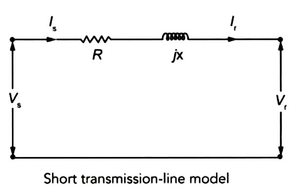
Ques.36. The arc voltage produced in A.C circuit breaker is always
- In phase with the arc current
- Lagging the arc current by 90°
- Leading the arc current by 90°
- None of the above
Answer.1. In phase with the arc current Explanation:- An electric arc is a visible plasma discharge between two electrodes that is caused by electrical current ionizing gasses in the air. The electric arc is a self-sustained electrical discharge that exhibits a low voltage drop, is capable of sustaining large currents, and behaves like a non-linear resistor. As the volt-ampere characteristics of an arc voltage are negative i.e arc voltage is high when the arc current is low and vice-versa. In order to maintain the ionization of the gas, when the arc is effectively cooled, the magnitude of the arc voltage must increase. What this means is simply that as the arc cools, the cooling efficiency increases the deionization of the arc space, which in turn increases the arc resistance. As a consequence of the increase in resistance, the short circuit current and the phase angle are reduced and thus the likelihood of a successful interruption is significantly enhanced. The voltage drop across the arc is called arc voltage. As the arc path is purely resistive, the arc voltage is in phase with the arc current. The magnitude of the arc voltage is very low, amounting to only a few percent of the rated voltage. A typical value maybe about 3 percent of the rated voltage.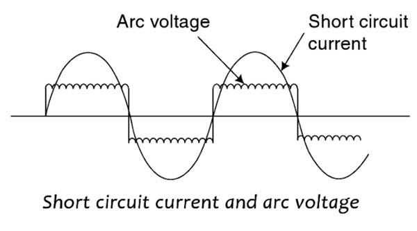
Ques.37. IDMT Relay stands for
- Inverse Divide Minimum Time
- Inverse Define Minimum Time
- Inverse Definite Minimum Time
- Inverse Differentiate Minimum time
Answer.3. Inverse Definite Minimum Time Explanation:- Inverse Definite Minimum Time (IDMT Relay):- In this Relay, the time of operation is approximately inversely proportional to the smaller value of current or other quantity causes operation intense to be definite time as the value increase without limit
Ques.38. Insulation resistance of high voltage circuit breakers is carried out when
- The circuit breaker is open
- The circuit breaker is closed
- Any of the above
- None of the above
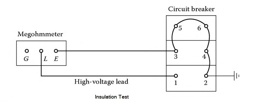
Answer.3. Any of the above Explanation:- The insulation resistance measurement test may be conducted on all types of electrical switchgear using the insulation resistance megohmmeter commonly known as the MEGGER. The insulation resistance test consists of applying voltage (600-l0,000V DC) to the apparatus to determine the megohm value of resistance. This test does not indicate the quality of primary insulation. Several factors should be remembered when performing this test. The first is that this test can indicate low values of insulation resistance because of many parallel paths. The other is that an insulation system having low dielectric strength may indicate high resistance values. In view of this, the test results should only be interpreted for comparative purposes. This does not indicate the quality of the primary insulation system from the point of view of dielectric withstand ability. The connection diagram for making this test on a power circuit breaker is shown in Figure. When performing insulation testing, it is recommended that auxiliary equipment, such as potential transformers and lightning arresters, be removed from the stationary switchgear. Insulation resistance tests are made with the circuit breaker in the open and closed position, whereas the insulation test for the switchgear bus is made with one phase to ground at a time, with the other two phases grounded. The procedure for this test is as follows:Insulation Resistance Measurement Test
Ques.39. H.R.C. fuses provide the best protection against
- Overload
- Reverse current
- Open-circuits
- Short-circuits
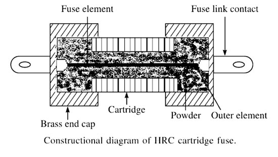
Answer.4. Short-circuits Explanation:- High rupturing capacity (HRC) Fuse links provide complete protection to cables, switchgear, control gear, and other equipment by limiting the current, both in magnitude and in the time duration, that can pass through these devices in the circuit. It is always desirable to protect a power circuit against short circuits separately. HRC fuses are the immediate answer to such a requirement for small and medium-sized LV motors. They have a delayed action characteristic under an over-load and are instantaneous against a shortcircuit condition and thus inherit the quality of discrimination. They reduce the electromagnetic and thermal stresses and enhance the withstand capacity of the Protected equipment for higher fault levels. These type of fuses comprises a high-grade ceramic body within which fuse elements are placed and welded to the endplates. The assembly is filled with dry granular quartz sand. In the event of flow of high short circuit current, this quartz sand solidifies forming high resistance glass in the arc path to ensure effectively are quenching in optimum time. The fuse elements are the non-deteriorating type which means that they maintain their characteristics over the long service period. The fuse element is either pure silver or bimetallic in nature. Silver-plated tag contacts provide good contact with fuse base and keep the fuse temperature low. These types of fuses can be plugged in and out even when hot or in service with an insulated fuse puller. The fuse element in the form of a long cylindrical wire is not used because after melting, it will form a string of droplets and an arc will be struck between each of the droplets. The shape of the fuse element depends upon the characteristic desired. When the fuse carries a normal rated current, the heat energy generated is not sufficient to melt the fuse element. But when a fault occurs, the fuse element melts before the fault current reaches its first peak. As the element melts, it vaporizes and disperses.HRC Fuses
Advantages of HRC Fuses
Disadvantages of HRC Fuses
Applications of HRC Fuses
Ques.40. The ground wire should not be smaller than No ______ copper.
- 2
- 4
- 6
- 10
Answer.4. 10 Explanation:- Fault currents flowing in the grounding system may cause dangerous differences in potential between the grounded instrument cases and other metal objects, presenting serious shock hazards to the patient. These differences in potential may result from high fault currents flowing in electric conduits or metal raceways sometimes used for the grounding conductor, or in long runs of small ground wires, especially if the wires have defective splices. As noted in Sec. 720.4, “Conductors shall not be smaller than 12 AWG copper or equivalent. Conductors for appliance branch circuits supplying more than one appliance or appliance receptacle shall not be smaller than 10 AWG copper or equivalent.” The hazard from ground currents can be reduced by using a continuous insulated short length of copper ground wire (not smaller than stranded No. 12 AWG) connecting each receptacle, or cluster of receptacles to the patient’s grounding bus, and by a similar copper ground wire (not smaller than No 10 AWG connecting the grounding bus to the room grounding bus, and then to the nearest available effectively grounded structural metal member of the building to the nearest grounded water piper and to the grounding bus at the main building supply panel.
