Ques.81. Overvoltage protection is recommended for
- Hydro-electric generators
- Steam turbine generators
- Gas turbine generators
- All of the above
Answer.1. Hydro-electric generators
Explanation:-
Apart from transient overvoltage caused by lightning, etc., overvoltage can be associated with over-speed or it can be caused by a defective voltage regulator.
The protection against transient high frequency or impulse overvoltage due to lightning and switching surges can be offered by lightning arrestors. But overvoltage relay is required to protect the stator conductor insulation of the generator against power-frequency overvoltages.
On modern steam-driven generators, the voltage regulators act sufficiently fast to prevent serious overvoltage from occurring when the generator loses its load and terminal voltage increases either due to acceleration or as a consequence of line charging current.
The most suitable overvoltage relay will have two units; an instantaneous unit tripping on 25% (steam) or 40% (hydra) overvoltage and an inverse time unit starting at 10% overvoltage. The relay will be energized from a PT secondary.
In the modern protective scheme, the operation of an overvoltage relay, initially causes the alarm to be sounded and thus warns the operator. Should the automatic voltage regulator not restore the voltage to normal within the preset time, the machine has to be tripped completely as the overvoltage can deteriorate the generator insulation. Thus overvoltage protection is a Class A protection.
Alternating-current overvoltage protection is IS recommended for hydroelectric generators subject to Overspeed and consequent overvoltage on the loss of load. Some hydroelectric generators can go up to 140% more of rated speed when the full load is dropped. The voltage may reach 200% or more.
With a hydro-generator, volts per hertz protection may not detect the problem, since the overvoltage will result in an Overspeed and consequently the V/Hz operating settings may not be exceeded. In general, overvoltages are not a problem with steam or gas turbines since the rapid response of the speed governor and the voltage regulator prevent the occurrence. In addition, most excitation systems on synchronous generators have integral V/Hz limiters that prevent overvoltage from occurring.
Ques.82. In a thyrite lightning arrester the resistance
- Decrease linearly with the applied voltage
- Is high at low current and low at high current
- Is low at low current and high at high current
- Increase linearly with the applied voltage
Answer.2. Is high at low current and low at high current Explanation:- Thyrite is a mixture of a certain type of clay and carborundum. It has a non-linear property which at lower voltages acts as a non-conducting or insulating material and at higher voltages acts as a good conductor. The resistance offered by thyrite is voltage-dependent. Whenever the voltage is doubled, the resistance decreases so as to pass more current through it. Hence, during a lightning surge, it allows the current through it to the earth. Once the surge has passed away, the thyrite regains its original resistance value at normal voltages without any permanent chemical changes. The basic cells of thyrite are used inside this type of lightning Arrester. A thyrite lightning arrester consists of a number of discs stacked one above the other and electrically in series with air gaps in the series-gap unit. The discs and series-gap units are assembled inside a wet-process porcelain container. At the top and bottom, there are two aluminum castings. These castings are cemented to the porcelain container. The discs are kept in position by the spring underneath the top cap casting. The cap of the casting is connected to the line by a terminal at the top. The bottom case is connected to the earth. During the surge, the gap spark-over and the thyrite discs offer relatively low resistance to the flow of surge current. After the surge disappears, the discs regain their original high resistance, and the series gap together with this high resistance does not allow any flow of current under the normal operating conditions. Thyrite is used widely in lightning arresters. It does not follow Ohm’s law, for each time the voltage is doubled the current increases 12.6 times. This means the resistance decreases as the current and voltage increaseThyrite Lightning Arrester
Ques.83. Over fluxing protection is recommended for
- Distribution transformer
- Generator transformer of the power plant
- Auto-transformer of the power plant
- Station transformer of the power plant
Answer.2. Generator transformer of the power plant Explanation:- Over fluxing The transformers in generating stations need protection against the risk of damage, which may be because when they are operated at flux density levels significantly greater than the designed values. These conditions are most likely to arise when the unit is on an open circuit with the generator field energized, the speed of the machine is considerably below the synchronous speed and the regulator is trying to bring the voltage to the normal rated value. This may result in an unduly large value of V/f and hence a flux. The flux density in the transformer core is proportional to the ratio of the voltage to frequency i.e. V/f. The power transformers are designed to work with a certain value of flux density in the core. In the generator transformer unit, if full excitation is applied before the generator reaches its synchronous speed then due to high V/f the over fluxing of the core may result. Higher core flux means more core loss and overheating of the core. The saturation of the magnetic circuit is also the probable cause for the over fluxing operation. Over fluxing is a phenomenon by which the flux linked with the primary and the secondary of the transformer increases to an abnormally high value. This can have a profound effect on the efficiency and life of a transformer mainly because of the heating and magnetostrictive effects. An increase in magnetic flux densities increases the iron losses and magnetizing current of the transformer. The core and core bolts, as a result, get heated and the insulation of laminations is affected. This can lead to permanent core damage and short circuit faults due to damaged insulation. Over fluxing Relay This is used for the protection of power transformers from over fluxing which is a result of overvoltage and causes heating of the transformer and saturation. The winding temperature relay can detect heating but cannot detect the saturation of the core. The transformer will fail to operate if saturated. This protection is one of the functions in the comprehensive transformer protection relay used on power transformers. The setting is based on the ratio of voltage and frequency. The flux is directly proportional to voltage and inversely proportional to the frequency. Therefore the relay setting is a volts/hertz ratio.
Ques.84. Series capacitors are used to
- Compensate for line inductive reactance
- Compensate for line capacitive reactance
- Improve line voltage
- None of the above
Answer.1. Compensate for line inductive reactance Explanation:- A series capacitor is used in a transmission line to reduce the inductive reactance +jXL. As shown below, the addition of a series capacitor −jXC partially cancels the series inductive reactance: The series capacitors in the transmission lines are used for the following: 1. Increase in Power Transfer Capability – The power transfer over a line is given by: P = (VsVr/X) Sin δ Where, P – Power transferred per phase (W) If a capacitor having capacitance reactance XC is connected in series with the line, the reactance of the line is reduced from XL to (XL − XC). The power transfer will increase due to the decrease in reactance from XL to (XL − XC). 2. Improvement in System Stability – For the same power transfer and for the same value of sending and receiving end voltage, the phase angle δ in the case of the line having series capacitors is less than that for the line without the series capacitor. The reduced value of δ gives higher stability. 3. Load Division among Parallel Line – Series capacitors are used in transmission systems for improving the load division between parallel lines. When the new line with a large power transfer capability is paralleled with an already existing line, then it is difficult to load the new line without overloading the old line. In such case, the series capacitor reduces the reactance and proper load division among parallel circuits can be done easily. Load division increases the power transfer capability of the system and reduced losses. 4. Control of Voltage – In the series capacitor, there is an automatic change in Var (reactive power) with the change in load current. Thus the drops in voltage levels due to sudden load variations are corrected instantly.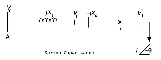
Vs – sending-end phase voltage (V)
Vr – receiving-end phase voltage
X –Reactance of the line (X=XL without the series capacitor. X = (XL − XC) with a series capacitor)
δ – phase angle between Vs & Vr.
Ques.85. Admittance relay is _______ relay.
- Impedance
- Distance
- Non-directional
- None of the above
Answer.2. Distance Explanation:- Distance Relays Distance relays respond to the voltage and current, i.e., the impedance, at the relay location. The impedance per mile is fairly constant so these relays respond to the distance between the relay location and the fault location. As the power systems become more complex and the fault current varies with changes in generation and system configuration, directional overcurrent relays become difficult to apply and to set for all contingencies, whereas the distance relay setting is constant for a wide variety of changes external to the protected line. There are three general distance relay types as shown in Fig. Each is distinguished by its application and its operating characteristic. Impedance Relay The impedance relay has a circular characteristic centered at the origin of the R-X diagram. It is nondirectional and is used primarily as a fault detector. Admittance Relay The admittance relay is the most commonly used distance relay. It is the tripping relay in pilot schemes and as the backup relay in step distance schemes. Its characteristic passes through the origin of the R-X diagram and is therefore directional. In the electromechanical design, it is circular, and in the solid-state design, it can be shaped to correspond to the transmission line impedance. Reactance Relay The reactance relay is a straight-line characteristic that responds only to the reactance of the protected line. It is nondirectional and is used to supplement the admittance relay as a tripping relay to make the overall protection independent of resistance. It is particularly useful on short lines where the fault arc resistance is the same order of magnitude as the line length. MHO Relay MHO relay is a high-speed relay and is also known as an admittance relay. lt is well known that a long line is less stable than a short line; that is, a long line has a larger swing angle δmax compared to a short line. The short line has a higher Pmax than that of a long line.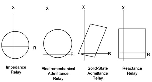
Why is Mho’s Relay used for Long Transmission Line?
Ques.86. The material used for fuse must have
- The low melting point and high specific resistance
- The low melting point and low specific resistance
- High melting point and low specific resistance
- Low melting point and any specific resistance
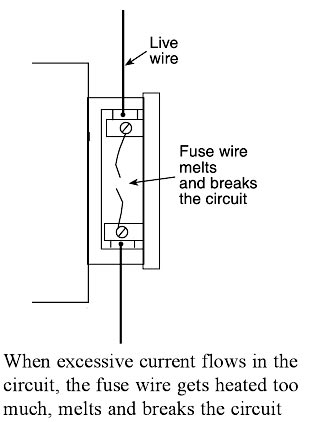
Answer.2. The low melting point and low specific resistance Explanation:- Fuse is the current interrupting device that breaks or opens the circuit (in which it is inserted) by fusing the elements when the current in the circuit exceeds a certain value. Fuse is the simplest and cheapest device used for interrupting an electrical circuit under the condition of short-circuiting, or excessive overload, current magnitudes. A fuse is a safety device having a short length of a thin, tin-plated copper wire having a low melting point, which melts and breaks the circuit if the current exceeds a safe value. The thickness and length of the fuse wire depend on the maximum current allowed through the circuit. An electric fuse works on the heating effect of current. The fuse for protecting our domestic wiring is fitted just above our main switch on the switchboard. A fuse wire is connected in series in the electric circuits. The main fuse in domestic wiring consists of a porcelain fuse holder H having two brass terminals T1 and T2 in it. This is connected in the live wire. The other part of the fuse is a removable fuse grip G which is also made of porcelain. The fuse grip has a fuse wire fixed in it. When fuse grip is inserted in the fuse holder as shown in Figure, then the circuit of our domestic wiring is completed. So, under normal circumstances when the current is within the limit, then the fuse wire is intact and electric current is available in our wiring. When a short circuit takes place, or when overloading takes place, the current becomes large and the fuse wire too much. Since the melting point of fuse wire is much lower than copper wires, the fuse wire melts and breaks the circuit as shown in Figure. When the fuse wire breaks, the electricity supply is automatically switched off before any damage can be done to the rest of the wiring (or the electric appliances being used). We will now give some important points about the fuse wire to be used in electrical circuits. First of all, we should know why we use a thin wire as a fuse wire and not a thick wire. We use a thin wire in a fuse because it has a much greater resistance than the rest of connecting wires. Due to its high resistance, the heating effect of current will be much more in the fuse wire than anywhere else in the circuit. This will melt the fuse wire whereas other wirings will remain safe. We should not use a thick wire as a fuse wire because it will have low resistance and hence it will not get heated to its melting point easily. The fuse wire is usually made from tin-plated copper wire having a low melting point so that it may melt easily. A pure copper wire cannot be used as a fuse wire because it has a high melting point due to which it will not be easily when a short circuit takes place. Fuse wire is made with an alloy of lead and tin having a low melting point and low resistance (although the resistance of fuse wire is higher than that of electrical appliances). If due to any malfunction or fault, excessive current begins to flow through the circuit, the fuse wire immediately melts due to the heat generated by the flowing current. The circuit is broken and the excess current, which may damage equipment is prevented from flowing. It is used for Overload and for short-circuit protection in high voltage (upto 66 kV) and for low Voltage (upto 120 V – 240 V) installations/circuits. Characteristics of a fuse are:-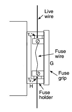
Ques.87. If the fault occurs near the impedance relay, the VI ratio will be
- Constant for all distances
- Lower than that of if the fault occurs away from the relay
- Higher than that of if the fault occurs away from the relay
- None of the above
Answer.2. Lower than that of if the fault occurs away from the relay Explanation:- Distance Relaying Overcurrent relays, differential relays, or directional relays operate if the amount of current or power exceeds a preset value. But the distance relays are governed by the ratio of the applied voltage to the current. These relays include impedance relays, reactance relays, and mho relays. The distance relaying scheme entails the use of a dual input comparator, and it works on the basis of a working torque, which is produced by the current coil and voltage coils. For example, an impedance relay operates when the ratio V/I is less than a predetermined value. The current coil of the relay receives the line current while the voltage coil of the relay is supplied with the bus voltage. The reach of the distance relay cannot be shifted by the switching operation or a change in the generation capacity or the type of fault. Phase distance relays, which are used for the phase fault involving two or more phases, are fed with delta voltage and delta current (line voltage and line current). For the line to ground fault, the relay is supplied with star voltage and star current, i.e. the phase voltage and phase current. Application of Impedance Relay The figure shows a simple application of the impedance relay in the transmission line. The protected zone impedance is ZL if the fault occurs say at point F1 inside the protected zone. The relay compares the impedance of the part of the line between fault point F1 and the place where the relay is installed (ZF = V/I). The relay will operate because of ZF < ZL . But the relay will not operate if the fault occurs outside the protected zone because in that situation ZF > ZL. Distance relaying works both as the primary as well as the backup protection. Distance relays are of two types: the definite distance relay operates instantaneously for a fault occurring up to a predetermined distance from the relay and the time distance relay is used when the operation of time is proportional to the distance of the fault point from the relay. The time distance relay operates faster in case of a fault occurring closer to the relay than that occurring farther away from the relay fault closer to the relay operates earlier than the fault farther away from the relay. If the relay closer to the fault point fails, the next relay works as backup protection.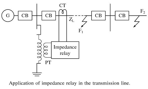
Ques.88. The torque produced in induction type relay (shaded pole structure) is
- Inversely proportional to the current
- Inversely proportional to the square of the current
- Proportional to the current
- Proportional to the square of the current
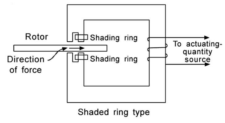
Answer.4. Proportional to the square of the current Explanation:- Induction Type Relays The induction type relays are also called magnitude relays. These relays work on the principle of the induction motor or an energy meter. In these relays, a metallic disc is allowed to rotate between the two electromagnets. The coils of the electromagnets are energized with the help of alternating currents. The torque is produced in these relays due to the interaction of one alternating flux with eddy currents induced in the rotor by another alternating flux. The two fluxes have the same frequency but are displaced in time and space. As the interaction of alternating fluxes is the base of operation of these relays, these are not used for the d.c. quantities. These are widely used for protective relaying involving only a.c. quantities. Based on the construction, the various types of induction type relays are Shaded pole type It consists of an aluminum disc that is free to rotate in an air gap of an electromagnet. The part of the pole face of each pole is shaded with the help of a copper band or ring. This is called a shading ring. The total flux produced due to the alternating current split into two fluxes displaced in time and space due to the shading ring. Due to the alternating flux, e.m.f. gets induced in the shading ring. This e.m.f. drives the currents causing the flux to exist in the shaded portion. This flux lags behind the flux in the unshaded portion by an angle α. The torque produced in the shade pole type relay is T ∝ KI2 Where K = constant I = current in the relay Hence in shaded pole type relay, the torque is directly proportional to the square of the current
Ques.89. The steady-state stability of the power system can be increased by
- Connecting lines in parallel
- Connecting lines in series
- Using machines of high impedance
- Reducing the excitation of machines
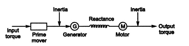
Answer.1. Connecting lines in parallel Explanation:- According to the definition, power system stability is the ability of the power system to remain in a balanced condition during the normal operation of the system and to bring back balanced conditions within the minimum possible time after the occurrence of disturbance. In general, in the literature, four different types need to be dealt with steady-state stability, dynamic stability, transient stability, and voltage stability. Steady-State Stability:– Steady-state stability may be defined as the ability of a power system to maintain synchronism between machines within the system and external tie-lines, for small and slow normal load fluctuations. or A power system is a steady-state stable for a particular steady-state operating condition if, following any disturbance, it reaches a steady-state operating condition that is close to or identical to the pre-disturbance operating condition. Steady-state stability can be improved by Steady-state stability is given by P = EV/X Where E = Internal machine voltage V = Terminal voltage X = Reactance As is clear from Eq. the methods of improving steady-state stability limit of a system are to reduce X and increase either or both E and V. If the transmission lines are of sufficiently high reactance, the stability limit can be raised by using two parallel lines which incidentally also increases the reliability of the system. Series capacitors are sometimes employed in lines to get better voltage regulation and to raise the stability limit by decreasing the line reactance. Higher excitation voltages and a quick excitation system are also employed to improve the stability limit.Stability Limit
Ques.90. Stability of a system is not affected by _____
- Reactance of Line
- Losses
- Reactance of generator
- Output Torque
Answer.1. Reactance of line Explanation:- The stability of an interconnected power system is its ability to return to normal or stable operation after having been subjected to some form of disturbance. Conversely, instability means a condition denoting loss of synchronism or falling out of step. Stability considerations have been recognized as an essential part of power system planning for a long time. The stability limit is the maximum power that can be transferred in a network between sources and loads without loss of synchronism. The steady-state limit is the maximum power that can be transferred without the system becoming unstable when the load is increased gradually under steady-state conditions. The transient limit is the maximum power that can be transferred without the system becoming unstable when a sudden or large disturbance occurs. Synchronous stability may be divided into two main categories depending upon the magnitude of the disturbance. Steady-state stability:- Steady-state stability refers to the ability of the power system to regain synchronism after small and slow disturbances, such as gradual power changes. Steady-state stability is subdivided into static stability and dynamic stability. 1. Static stability. Static stability refers to inherent stability that prevails without the aid of automatic control devices such as governors and voltage regulators. 2. Dynamic stability. Dynamic stability, on the other hand, denotes artificial stability given to an inherently unstable system by automatic control devices. Dynamic stability is concerned with small disturbances lasting for times of the order of 10-30 s with the inclusion of a static control device. Transient stability:- Transient stability is the ability of the system to regain synchronism after a large disturbance. The large disturbance can occur due to sudden changes in application or removal of large loads, line switching operations, faults on the system, the sudden outage of a line, or loss of excitation. Transient stability studies are needed to ensure that the system can withstand the transient conditions following a major disturbance. Stability studies are helpful for the following purposes: The seven essential factors affecting stability are broadly classified into two parts Suppose In case of the generator connected radially without automatic voltage regulators, the instability will occur which is due to a lack of sufficient synchronizing torque. The Maximum Power transfer without the loss of stability is given by {P_{12}} = \dfrac{{{V_1} \times {V_2}}}{{{X_L}}}\sin 90P12 =XL V1 ×V2 sin90 The reactance can be reduced by either increasing the sending end voltage or receiving end voltage Thus increasing the stability of the system.