
Ques.11. Relays can be designed to respond to changes in
- Resistance, reactance or impedance
- Voltage and current
- Temperature
- All of the above
Answer.4. All of the above Explanation:- Relays are switches that open and close circuits electromechanically or electronically. Or An electric device that is designed to interpret input conditions in a prescribed manner and after specified conditions are met to respond to cause contact operation or similar abrupt change in an associated electric control circuit. Inputs are usually electric but may be mechanical, thermal, or other quantities. A relay may consist of several units, when responsive to specified inputs, the combination providing the desired performance characteristic. The relays can be electrical, thermal, pneumatic, hydraulic, and other. Some of the automatic relays used to control and protect electrical equipment are described in the following paragraphs. Thermal overload relays are provided on starters to prevent equipment from burning out if abnormal operating conditions increase the load beyond the pump’s design capacity. When current is excessive, the relays (sometimes called heaters) placed on each phase of the power supply open the control circuit and stop the motor. These relays are normally set to stop the motor when the current exceeds the design load by 25 percent. Fuses or circuit breakers are placed in the main power wiring to each motor to protect against short circuits. They are normally located in the safety switch just ahead of the starter. Overcurrent relays are often referred to as overload relays. Their purpose is to sense current surges in the power supply and to disconnect the motor if a surge occurs. They can be fitted with time-delay or preset thermal-overload mechanisms. The overload relays may reset automatically or they may require manual resetting after they are tripped. Voltage relays are frequently used to detect a loss of power and to initiate a switchover to an alternate power source. Undervoltage relays are also used to shut down motors if the voltage drops too low. Voltage relays generally have a timing mechanism that allows minor functions (ones that won’t damage the motor) to continue before power is actually disconnected from the motor. Frequency relays respond to changes in the frequency (in cycles per second) of an AC power supply. They are most often used where local power generation is involved. Frequency relays are also used on synchronous motor starters to sense when the motor has reached synchronizing speed. Phase-reversal relays are installed to detect whether any two of the three lines of a three-phase power system are interchanged. If the phase sequence should be reversed, all motors will run backward. A phase-reversal relay senses this change and opens the control circuit to disconnect the motors. A phase reversal can be particularly serious for deep-well pump applications. The pump shafting can become unscrewed, allowing the pump to fail. Loss-of-phase relays are installed in most wiring systems to detect the loss of one of the three phases. Loss of one phase is not unusual, and if the power is not cut off, the motor may burn out within a few minutes while operating on only two Phases. Differential relays are frequently used on large equipment or switchgear. These units check whether all of the current entering a system comes back out of the system. If it does not, the relay closes a contact that shuts down the equipment. An equipment shutdown by a differential relay indicates major trouble, so an electrician should always be called. Reverse-current relays sense a change in the normal direction of current or power flow and activate an alarm for the operator. They can also open circuits to isolate the faulty portion of the system. Time-delay relays are used when some condition needs to last for a specified length of time before some other action is begun. For example, if a pump motor must be given sufficient time to reach full speed before the discharge valve opens, a time-delay relay can be energized when the motor is started. The relay can be set to close its contacts several seconds later to activate the valve-opening control circuits.Relay
Ques.12. Overload relays are of ________ type.
- Solid-state
- Thermal
- Electromagnetic
- All of the above
Answer.4. All of the above Explanation:- One of the most important relays for the detection of abnormal conditions is the overload relay which is applied to the protection of motors. The overload relay differs from the overcurrent relay in the following ways. Whereas the overcurrent relay must operate quickly in times of around or less than 1 s the overload relay is associated with times of tens of seconds to several minutes. Overloads should not be confused with fuses or circuit breakers. Fuses and circuit breakers are designed to protect the circuit from a direct ground or short-circuit condition. Overloads are designed to protect the motor from an overload condition. Assume, for example, that a motor has a full-load current rating of 10 amperes. Also, assume that the motor is connected to a circuit that is protected by a 20-ampere circuit breaker. Now assume that the motor becomes overloaded and has a current draw of 15 amperes. The motor is drawing 150% of the full-load current. This much overload will overheat the motor and damages the windings. But, because the current is only 15 amperes, the 20-ampere circuit breaker does not open the circuit to protect the motor. Overload relays are designed to open the circuit when the current becomes 115% to 125% of the motor full-load current. The setting of the overload is dependent on the properties o the motor that is to be protected. Overload Properties There are certain properties that all overload relays must possess in order to protect a motor: Type of Overload relay Magnetic overload relay reacts only to current excesses is are not affected by temperature. As the name implies, thermal overload relays depend on the rising temperature caused by the overload current to trip the overload mechanism Thermal overload relays can be further subdivided into two types, melting alloy and bimetallic. In the melting alloy type, the heat produced by an overload current causes the solder to melt, permitting a spring-loaded ratchet wheel to turn and open a set of contacts. In the bimetallic strip type, the heat produced by overload current causes a deflection of the bimetal and opens a set of contacts. The beating elements of each type must be matched to the load. Each type is equipped with optional manual or automatic reset mechanisms. A solid-state relay (SSR) is an electronic switching device that switches on or off when a small external voltage is applied across its control terminals. When solid-state relays were introduced, they offered many advantages over electromechanical relays. The fundamental difference between electromechanical relays and solid-state relays is that electromechanical relays respond to input energy whereas solid-state relays process input voltage and current waveforms (signals). Solid-state relays are more accurate than electromechanical relays.Overload protection
Ques.13. Thermal overload relays are used to protect the motor against overcurrent due to
- Short-circuits
- Heavy loads
- Grounds.
- All of the above
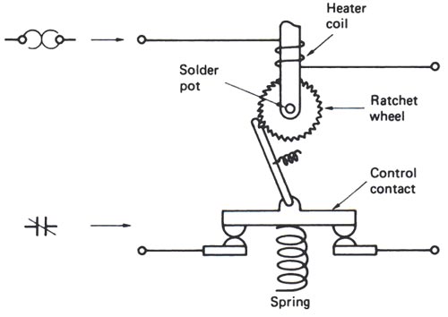
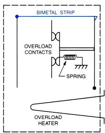
Answer.2. Heavy Loads Explanation:- The thermal protection switch protects against overload. Thermal breakers are used where overloads can be tolerated for an extended time, such as in commercial wiring and in the protection of motors, transformers, and tungsten lamp loads. The long temperature-dependent delay means the thermal breakers are not applicable to electronic systems and power conversion equipment protection, Thermal overload relay or switches can be divided into two types:- Melting overload Relay or Solder Melting Pot To create this type of overload, a bra shaft is placed inside a brass tube. In these overload relays (also referred to as “solder pot relays”), the motor current passes through a small heater winding. The heating element is connected in series with the motor. The current that flows through the motor windings also flows through the heating element. The heating element is calibrated to produce a certain amount of heat when a predetermined amount of current flows through it. As long as the current flowing through it does not exceed a certain amount, there is not enough heat produced to melt the solder. Under overload conditions, an excessive amount of current will flow through the heater causing excessive heat the heat causes a special solder to melt, allowing a ratchet wheel to spin free, opening the contacts. When this occurs, the relay is said to ” trip.” To obtain appropriate tripping current for motors of different sizes, of different full-load currents, a range of thermal units (heaters) is available. The heater coil and solder pot are combined in a one-piece, no-tamperable unit. The heat transfer characteristic and the accuracy of the unit cannot be accidentally changed, as is possible when the heater is a separate component. Melting alloy thermal overload relays are “hand reset,” thus after they trip they must be reset by a deliberate hand operation. A reset button is usually mounted on the cover of enclosed starters. Thermal units are rated in amperes and are selected on the basis of motor full-load current. Bimetal type Overload Relay The bimetal type of overload operates very similarly to the solder-melting type except a bimetal strip is used to cause the contacts to open. In this unit, the bimetal strip is used to mechanically hold the spring-loaded contacts closed. If the current flow through the heater becomes excessive the bimetal strip will warp and permit the spring to open the contacts. After the overload unit has tripped the bimetal strip must be allowed some time to cool before it can be reset. This type of unit has an advantage over the solder-melting type in that it, be adjusted for manual reset or automatic. The solder-melting type of overload must be manually reset.
Ques.14. The magnetic circuit breaker has ______ trip action.
- Delayed
- Instantaneous
- Short
- None of the above
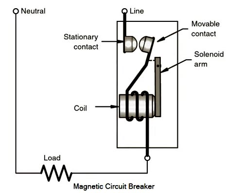
Answer.2. Instantaneous Explanation:- This device relies upon the magnetic effect of a current-carrying conductor for its operation. If the current flowing through a thick coil of wire, in series connection with the circuit, rises to an excessive value, the magnetic effect associated with the current causes a moveable metal-core to be drawn into the coil. The metal then strikes a bar, which operates a trip mechanism, causing the circuit to be opened and the current flow to be stooped. Because magnetic-type circuit breakers do not depend on heating a bimetallic strip, there is a very little time delay in the opening of the contacts when an overload occurs. For this reason, they are often referred to as instantaneous circuit breakers. As current flows through the circuit, a magnetic field is established around the coil. The magnetic field attracts the metal arm of a solenoid. If the magnetic field becomes intense enough, the metal arm mechanically opens the contacts of the circuit breaker. Circuit breakers that operate on this principle are referred to as magnetic circuit breakers. Magnetic circuit breakers are designed to open quickly (“instantaneously”) under short-circuit conditions. The instantaneous trip current usually is on the order of 6 to 10 times (6x, or 600%, to 1ox, or 1000%) the current rating of the circuit breaker. A typical thermal circuit breaker will open a 10,000-A fault in about 40 or 50 ms, but a magnetic circuit breaker will open the same fault in about 10 ms. Under higher short-circuit current conditions, the operating speed of magnetic circuit breakers may be as fast as 3 to 4 ms.Electromagnetic circuit breaker
Ques.15. D.C shunt relays are made of
- Few turns of thin wire
- Few turns of thick wire
- Many turns of thin wire
- Many turns of thick wire
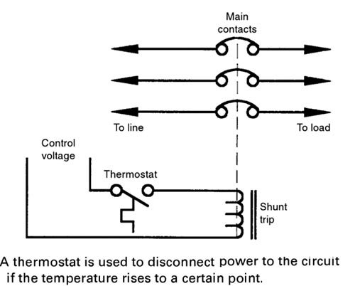
Answer.3. Many turns of thin wire Explanation:- Shunt relays are the auxiliary device used in conjunction with a circuit breaker which is similar to shunt contractors, except that they are required to handle only small amounts of current, since they commutate the coils of other relays and contractors, and do not handle the motor current. Therefore they are made of thin wire of many turns. Some circuit breakers contain a small solenoid coil known as a shunt trip. Shunt trips are used to open the circuit breaker contacts by energizing the solenoid from an external source. Assume, for example, that it is desirable to disconnect the power to a circuit if the temperature rises above a certain level. If the circuit breaker protecting the circuit contains a shunt trip, a thermostat can be connected in series with the solenoid. If the temperature rises above the desired level, the thermostat contacts will close and energize the coil, Figure. When the coil energizes, the circuit-breaker contacts will open and disconnect power to the circuit. A shunt trip relay completes the circuit between the control-power source and the solenoid coil. Shunt trips are used to trip a circuit breaker electrically from a remote location and consist of a momentary-rated solenoid tripping device mounted inside a molded case. The shunt trip can remotely trip the breaker but cannot remotely reclose the breaker. To recluse the breaker, the breaker handle must first be moved to the reset position and then to the “on” position.Shunt Trips
Ques.16. The function of the circuit breaker is
- To safeguard the circuit
- On and off the circuit
- To save human life
- None of these
Answer.1. To safeguard the circuit Explanation:- Circuit breakers are mechanical devices designed to close or open contacts members, thus closing or opening of an electrical circuit under normal or abnormal conditions. The main duty of the circuit breaker is
Ques.17. In order that current should flow without causing excessive heating or voltage drop, the relay contacts should
- Have low contact resistance
- Be clean and smooth
- Be of sufficient size and proper shape
- Have all above properties
Answer.4. Have all above properties Explanation:- The design of an electromagnetic relay is based on the construction of various components of that relay. The design considerations for the various components of an electromagnetic relay are, Coils: The coils carry the currents and should be designed by considering the temperature rise associated with the coil. The temperature rise limits the current rating of the coil. Practically the coils are tested for the test called voltage withstand test in which 2500 volts are applied to the coil for one second. The continuous and short-time current ratings are specified with the relay coil. For the current operated relay, the standard continuous current ratings are 0.5 A, 1 A and.5 A while for the voltage-operated relay the standard voltage between the lines is 110 V. Movable Assembly: The inertia of the movable assembly must be as low as possible for the fast operation of the relay. Thus the parts used are very light for the movable assembly. Similarly, for the fast operation, the distance of travel is also minimized. Relay Contact: This is the most important part of the relay. The relay contacts must be robust as the contacts must perform make and break duty successfully. This is difficult because for making relay sensitive, the parts used in the moving system are light in weight. Hence seal in contact arrangement is used. This arrangement prevents the opening of relay contacts for the flow of trip current. The important design considerations of the relay contacts are, The materials which are preferred for the relay contacts are silver due to low resistance and self-cleaning property, alloys of silver such as cadmium silver oxide for high current applications, gold~silver~platinum alloys for low current applications. Bearings: The pivot and jewel bearings are preferred for induction relays. The jewels absorb the shocks as spring mounted. The pin bearings and knife-edge bearings are used for armature relays. Cases: The cases used are of the same width and depth The length depends on the type and application of the relay. The cases are usually flush-mounted. Nowadays cases of pressed steel cast aluminum or plastic are used. These are dust-proof cases. Operation Indicator: This is a colored flag. When the relay operates, it is mechanically moved to indicate that the relay is operated. When the relay is reset the flag is reset manually. When the flag is operated the corresponding operation of the circuit breaker is assured. Adjustment of Reset: The adjustment of reset is achieved using tapped auxiliary potential transformers and resistors. In some relays, adjusting spring tension or air gap length adjustment is used for adjustment of reset.Design Considerations of Electromagnetic Relay
Ques.18. Circuit breakers usually operate under
- Transient state of short-circuit current
- Sub-transient state of short-circuit current
- The steady-state of short-circuit current
- After D.C component has ceased
Answer.1. Transient state of short-circuit current Explanation:- Fault current is divided into phases: Subtransient, Transient, and Steady State. The Subtransient phase is defined as the level of fault current during the first few cycles of the fault current. The fault current is at its most severe level during this time period, and the DC decay is at its most rapid rate. So, while it is a severe level, it doesn’t last very long. The Transient phase is that period after the subtransient period and lasts until the current level decays to normal current levels. It is less severe but lasts longer than the subtransient phase. The circuit breaker operates at the transient phase. The Steady-State phase is the normal current level—the fault current has decayed fully.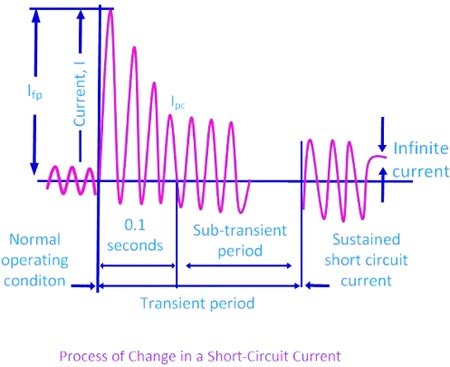
Ques.19. Circuit breakers are essentially
- Current carrying contacts called electrodes
- Arc extinguishers
- Circuits to break the system
- Transformers to isolate the two systems
Answer.1. Current carrying contacts called electrodes Explanation:- Circuit Breaker Circuit breakers (CBs) are mechanical systems designed to close or open an electrical circuit under normal or abnormal conditions. A relay senses the abnormal condition and sends a tripping signal to the circuit breaker for operation. The maximum value of current that a circuit breaker can interrupt without any damage is known as rupturing or interrupting current. A circuit breaker has two contacts: fixed contact and moving contact. During normal conditions, the contacts are in the closed position, whereas during abnormal conditions the contacts move to interrupt the circuit that results in an arc between the contact, as shown in Figure The circuit breakers are rated in MVA, and heavy-duty circuit breakers interrupt several thousand amperes of high short circuit currents. Arc Phenomenon Electrodes are the current-carrying contacts in the circuit breaker. They remain closed under normal conditions and separate to interrupt the circuit during abnormal conditions. When the current-carrying contacts separate, an arc forms. When the electrodes move the area of contact decreases. The high magnitude fault current causes an increase in current density which in turn increases the temperature between electrodes. The heat between the contacts has the ability to strike the electrons from air molecules or ionize the air surrounding the electrodes. This avalanche of free electrons in the medium is sufficient to carry charges and results in arc strikes. The arc has a low resistance path; therefore the current in the circuit remains continuous as long as the arc is sustained.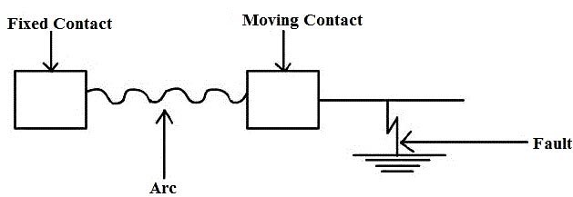
Ques.20. The current zero interruption, in oil and air blast circuit breakers, is achieved by
- Lengthening of the gap
- Cooling and blast effect
- Both 1 and 2
- Deionizing the oil with forced air
Answer.3. Both 1 and 2 Explanation:- Oil circuit breakers are the oldest type of circuit breakers that used oil as a dielectric or insulating medium for arc extinction. In the oil circuit breaker, the contacts of the breaker are made to separate within an insulating oil which has better insulating properties than air. Oil circuit breaker utilizes dielectric oil (transformer oil) for arc extinction. These circuit breakers can be employed for a voltage range of 33 kV to 22o kV and a breaking capacity of 1500 MVA to 7500 MVA Air blast circuit breaker:- In this type of circuit breaker, compressed air is used for the arc extinction. Hence it is called a compressed air circuit breaker. Those types of circuit breakers were employed in earlier days in indoor services for voltages ranging from 11 to 1100 kV with breaking capacities up to 25000 MVA. At high voltages, this type of circuit breaker is most suitable. In the modern-day, the air blast circuit breaker is also employed in high voltage circuits in the outdoor switchyard. The air blast circuit breakers are preferred for arc furnace duty and traction systems because they are suitable for repeated duty. These type of circuit breakers are finding their best application in systems operating in the range of 132 kV to 400 kV with breaking capacities up to 7000 MVA. After the occurrence of the fault, when the contacts of the CB begin to separate an arc is established in the contact gap. The two main causes responsible for generating an arc between the contacts of a CB are as follows: Potential difference (PD) between the contacts: When the contacts have a small separation, the PD between them is sufficient to maintain the arc. One way to extinguish the arc is to separate the contacts to such a distance that PD becomes inadequate to maintain the arc. However, this method is impracticable in a high voltage systems where the separation of many meters may be required. Ionized particles between contacts: The ionized particles between the contacts tend to maintain the arc. If the arc path is deionized, the arc extinction will be facilitated. This may be achieved by cooling the arc or by bodily removing the ionized particles from the space between the contacts. Methods of Arc Extinction There are two methods of extinguishing the arc in CB viz. In this method, arc resistance is made to increase with time so that current is reduced to a value insufficient to maintain the arc. Consequently, the current is interrupted or the arc is extinguished. The principal disadvantage of this method is that enormous energy is dissipated in the arc. Therefore, it is employed only in DC CBs and low-capacity AC CBs. The resistance of the arc may be increased by: Low Resistance or Current Zero Method This method is employed for arc extinction in AC circuits only. In this method, arc resistance is kept low until the current is zero where the arc extinguishes naturally and is prevented from restriking in spite of the rising voltage across the contacts. All modern high-power AC CB employ this method for arc extinction. In an AC system, the current drops to zero after every half cycle. At every current zero, the arc extinguishes for a brief moment. Now the medium between the contacts contains ions and electrons so that it has a small dielectric strength and can be easily broken down by the rising contact voltage known as restriking voltage. If such a breakdown does occur, the arc will persist for another half cycle. If immediately after current zero, the dielectric strength of the medium between contacts is built up more rapidly than the voltage across the contacts, the arc fails to restrike and the current will be interrupted. The rapid increase of dielectric strength of the medium near current zero can be achieved by
