Ques.71. The relay with inverse time is
- Directly proportional to the square of fault current
- Direct proportional to the of fault current
- Inversely proportional to the of fault current
- Inversely proportional to the square of fault current
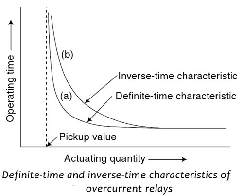
Answer.3. Inversely proportional to the of fault current Explanation:- The fundamental property of these relays is that they operate in a time that is inversely proportional to the fault current, as illustrated by the characteristic curves shown in fig. Their advantage over definite-time relays is that, for very high currents, much shorter tripping times can be obtained without risk to the protection selectivity. Inverse time relays are generally classified in accordance with their characteristic curve that indicates the speed of operation; based on this they are commonly defined as being inverse, very inverse, or extremely inverse. Inverse-time relays are also referred to as inverse definite minimum time or IDMT overcurrent relays. The definite time characteristic is simple. The time of operation is constant for any current above the pickup value, e.g. a relay is set to operate at 5 A (CT secondary current) and set at 0.5 sec definite time. The relay operation time will be 0.5 sec for 5, 10 or 20 A whatever is the current above the set current.Inverse-time relays
Ques.72. When the fault current is 2000 A, for a relay setting of 50% with CT ratio 500/5, the plug setting multiplier will be
- 16
- 12
- 4
- 8
Answer.4. 8 Explanation:- Plug setting multiplier of the relay is referred to as the ratio of the fault current in the relay to its pick-up current. The current transformer ratio is 500 / 5. So, the CT can be provided a rated current of 5 Amps to the relay coil. Now the relay setting is 50%, then the relay can be operated for 5 × ( 50 / 100 ) = 2.5 Amps. This is the pick-up current of that relay. We know that the fault current is 2000 Amps. Hence, the fault current in the secondary of the CT is 5 × ( 2000 / 500) = 20 Amps. Therefore PSM of the relay is, PSM = 20 / 2.5 = 8 That means the fault current in the secondary of the CT is 8 times greater than the operating current of the relay coil.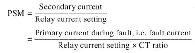
Ques.73. Which of the following devices will receive voltage surge first traveling on the transmission line?
- Lightning arresters
- Relays
- Step-down transformer
- Switchgear
Answer.1. Lightning arresters Explanation:- Lightning arresters are devices that help prevent damage to apparatus due to high voltages. The arrester provides a low-impedance path to the ground for the current from a lightning strike or transient voltage and then restores to normal operating conditions. Lightning arresters are connected between line and ground, and the arrester should be located as dose as possible to the terminals of the equipment being protected. For example, surge arresters used to protect the transformer in the substation may not protect the transformer if they are placed more than a meter away. If the transformer has primary fuses (which is most frequently done, the surge arresters can be placed on either side of the fuses; however, the most common practice is to place the surge arresters at the transformer terminals because this location provides the highest degree of protection for the transformer. Surge arrester leads should be as short and straight as possible. The leads must never be coiled or have any sharp bends. The lightning arrester should have the following characteristics: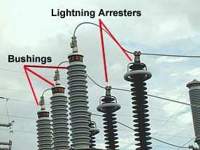
Ques.74. Which of the following parameter can be neglected for a short line?
- Inductance
- Capacitance
- Resistance
- Reactance
Answer.2. Capacitance Explanation:- Note:- In the case of short lines, power surges remain for a shorter period and hence, their effect is unimportant. The predominant factor is, therefore, the effect of arc resistance. The effect of power surges stays for a longer period in case of long lines and hence, a relay that is least affected by power surges is preferred for the protection of long lines. The MHO unit is less affected by power surges than the impedance and reactance relays and hence, it is best suited for the protection of long lines against phase As the line length is small and the voltage is also less, the capacitive effects are small. Due to this effect of capacitance is neglected. Thus only resistance and inductance is to be taken into account while analyzing short transmission lines.
Ques.75. Series reactors should have
- Low resistance
- High resistance
- Low impedance
- High impedance
Answer.1. Low resistance Explanation:- The extent of short-circuits at different locations can be reduced by connecting current limiting reactors also known as series reactors, A series reactor is an inductive coil having a large inductance with negligible resistance. These reactors are designed without saturation problems. By designing the reactance of the series reactor to a suitable value, short-circuit currents can be reduced to such a level that circuit breakers can handle them quite easily. As the present-day power system is largely interconnected, a fault at a particular location is contributed to by a large number of generators. These unacceptable short-circuit levels can be easily adjusted to an acceptable value by using series reactors. These reactors are connected in series with generators, feeders, transmission lines for limiting fault currents under short circuits. Series reactors should have linear magnetic characteristics under fault conditions. They are designed to withstand the mechanical and thermal effects of short circuits. Series reactors used in transmission lines have a fully insulated winding since both its ends should be able to withstand the lightning impulse voltages. The value of series reactance has to be judiciously selected because a higher value reduces the power transfer capability of the line. The main motive of using current limiting reactors is to reduce short-circuit currents so that circuit breakers with lower short circuit breaking capacity can be used. As the resistance of the reactor in comparison to their reactance is very small, the efficiency of the system is not affected appreciably.
Ques.76. Which of the following circuit breakers has high reliability and minimum maintenance?
- Air blast circuit breakers
- Circuit breaker with SF6 gas
- Vacuum circuit breakers
- Oil circuit breakers
Answer.2. Circuit breaker with SF6 gas Explanation:- SF6 gas circuit breakers are widely used for EHV applications today, as Sulphur hexafluoride(SF6) gas is an electronegative gas having excellent dielectric and arc quenching properties resulting in many advantages such as compactness and less maintenance of EHV circuit breaker The excellent insulating properties of SF6 gas make it possible to design circuit breakers with smaller overall dimensions, shorter contact gaps, which help in the construction of outdoor breakers with fewer interrupters, and the evolution of metal-enclosed SF6 gas-insulated switchgear.Advantages of SF6 Circuit Breaker
Disadvantages of SF6 Circuit Breaker:
Ques.77. Arc in a circuit breaker is interrupted at
- Zero current
- Maximum current
- Minimum current
- Maximum voltage
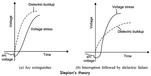
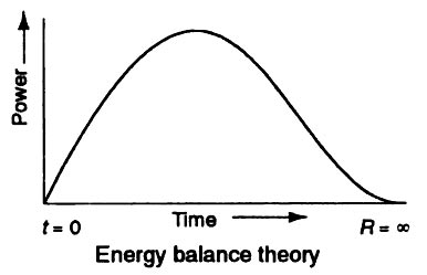
Answer.1. Zero current Explanation:- After the occurrence of the fault, when the contacts of the CB begin to separate an arc is established in the contact gap. The two main causes responsible for generating an arc between the contacts of a CB are as follows: Potential difference (PD) between the contacts: When the contacts have a small separation, the PD between them is sufficient to maintain the arc. One way to extinguish the arc is to separate the contacts to such a distance that PD becomes inadequate to maintain the arc. However, this method is impracticable in a high voltage system where the separation of many meters may be required. Ionized particles between contacts: The ionized particles between the contacts tend to maintain the arc. If the arc path is deionized, the arc extinction will be facilitated. This may be achieved by cooling the arc or by bodily removing the ionized particles from the space between the contacts. Methods of Arc Extinction There are two methods of extinguishing the arc in CB viz. In this method, arc resistance is made to increase with time so that current is reduced to a value insufficient to maintain the arc. Consequently, the current is interrupted or the arc is extinguished. The principal disadvantage of this method is that enormous energy is dissipated in the arc. Therefore, it is employed only in DC CBS and low-capacity AC CBs. The resistance of the arc may be increased by: Low Resistance or Current Zero Method This method is employed for arc extinction in AC circuits only. In this method, arc resistance is kept low until the current is zero where the arc extinguishes naturally and is prevented from restriking in spite of the rising voltage across the contacts. All modern high-power AC CB employ this method for arc extinction. In an AC system, the current drops to zero after every half cycle. At every current zero, the arc extinguishes for a brief moment. Now the medium between the contacts contains ions and electrons so that it has a small dielectric strength and can be easily broken down by the rising contact voltage known as restriking voltage. If such a breakdown does occur, the arc will persist for another half cycle. If immediately after current zero, the dielectric strength of the medium between contacts is built up more rapidly than the voltage across the contacts, the arc fails to restrike and the current will be interrupted. There are two theories to explain the zero current interruption of the arc. Recovery rate theory The arc is a column of ionized gases. To extinguish the arc, the electrons and ions are to be removed from the gap immediately after the current reaches a natural zero. ions and electrons can be removed either by recombining them into neutral molecules or by sweeping them away by inserting insulation medium (gas or liquid) into the gap. The arc is interrupted if ions are removed from the gap at a rate faster than the rate of ionization. In this method, the rate at which the gap recovers its dielectric strength is compared with the rate at which the restriking voltage (Transient voltage) across the gap rises. If the dielectric strength increases more rapidly than the restriking voltage, the arc is extinguished. If the restriking voltage rises more rapidly than the dielectric strength, the ionization persists and breakdown of the gap occurs, resulting in an arc for another half cycle. Energy balance theory The space between the contact contains some ionized gas immediately after current zero and hence, it has a finite post-zero resistance. At the current zero moments, power is zero because the restriking voltage is zero. When the arc is finally extinguished, the power again becomes zero, the gap is fully deionized and its resistance is infinitely high In between these two limits, first, the power increase reaches a maximum value, then decreases and finally reaches zero value. Due to the rise of restriking voltage and associated current energy is generated in the space between the contacts. The energy appears is in the form of heat. The circuit breaker is designed to remove this generated her as early as possible by cooling the gap, giving a blast of air or flow of oil at high velocity and pressure. If the rate of removal of heat is faster than the rate of heat generation the arc is extinguished if the rate of heat generation is more than the rate of heat dissipation, space breaks down again resulting in an arc for another half cycle.
Ques.78. The transmission line has a reflection coefficient as one
- Open circuit
- Short-circuit
- Long
- None of the above
Answer.1. Open circuit Explanation:- The ratio of the reflected wave to the incident wave is known as the reflection coefficient and is simply a measure of the quality of the match between the transmission line and the terminating impedances. In the general case, the amplitude of the wave reflected at the end of the transmission line is determined by the reflection coefficient, ρ (rho). The value of ρ depends on ZO and Zterms the termination impedance that appears at the end of the line: ρ = Reflection coefficient = (Zterms − ZO) ⁄ (Zterms + ZO) When a voltage wave with amplitude Vwave hits the end of a transmission line the wave with amplitude ρ · Vwave is reflected. Note that three simple cases match Zterms = ZO :- When a transmission line is terminated in its characteristic impedance, the reflection coefficient is 0. Zterms = 0:- The reflection coefficient of a short-circuited line is -1, producing a reflection of equal magnitude and opposite polarity. Zterms = ∞ :– The reflection coefficient of an open-circuited line is +1, producing a reflection of equal magnitude and the same Polarity.
Ques.79. What will be the reflection coefficient of the wave of the load connected to the transmission line if surge impedance of the line is equal to load?
- Zero
- Unity
- Infinity
- None of the above
Answer.1. Zero Explanation:- The ratio of the reflected wave to the incident wave is known as the reflection coefficient and is simply a measure of the quality of the match between the transmission line and the terminating impedances. In the general case, the amplitude of the wave reflected at the end of the transmission line is determined by the reflection coefficient, ρ (rho). The value of ρ depends on ZO and Zterms the termination impedance that appears at the end of the line: ρ = Reflection coefficient = (Zterms − ZO) ⁄ (Zterms + ZO) When a voltage wave with amplitude Vwave hits the end of a transmission line the wave with amplitude ρ · Vwave is reflected. Note that three simple cases match Zterms = ZO :- When a transmission line is terminated in its characteristic impedance, the reflection coefficient is 0. Zterms = 0:- The reflection coefficient of a short-circuited line is -1, producing a reflection of equal magnitude and opposite polarity. Zterms = ∞ :– The reflection coefficient of an open-circuited line is +1, producing a reflection of equal magnitude and the same Polarity.
Ques.80. A Buchholz relay is used for
- Protection of a transformer against all internal faults.
- Protection of a transformer against external faults.
- Protection of a transformer against both internal and external faults.
- Protection of induction motors.
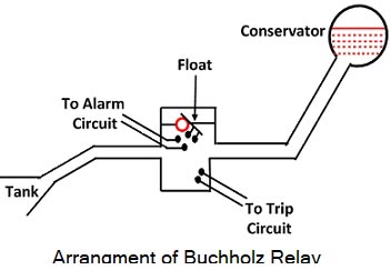
Answer.1. Protection of a transformer against all internal faults Explanation:- When a fault occurs inside the transformer tank, gas is usually generated, slowly for an incipient fault and violently for heavy faults. Most of the short circuits are developed by impulse breakdown [insulation failure] between adjacent turns at the end turns of the winding. The heat produced by the high local current causes the transformer oil to decompose and produce gas which can be made used to detect the winding faults. Buchholz relay is the simplest form of protection which is commonly used in all transformers provided with the conservator. It will act (or) close the breaker circuit, whenever there is a sudden rise of oil pressure inside the transformer or there is more gas collection. So, this device will only sense the internal fault of transformers.